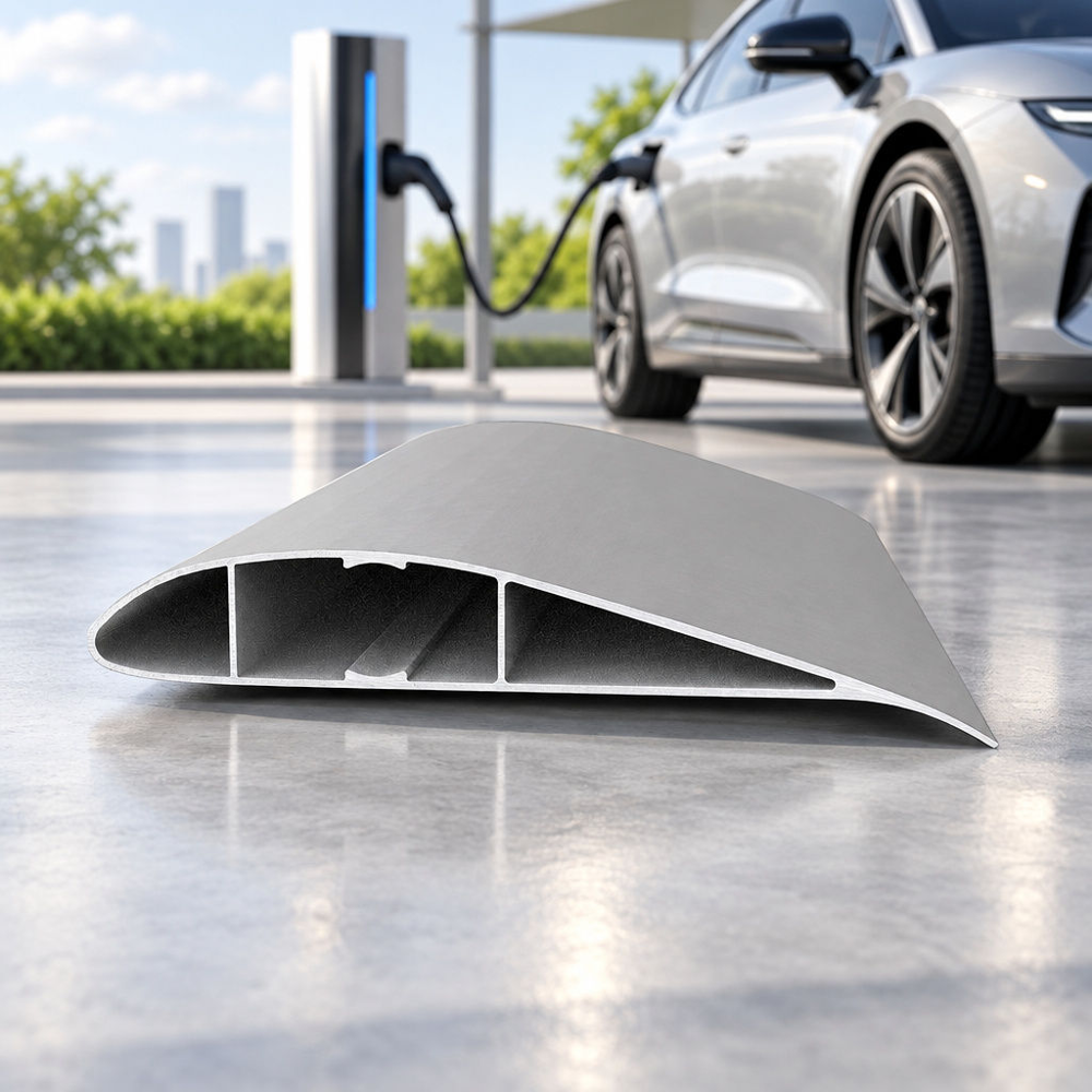
Every kilogram added to a battery pack forces automotive engineers into a costly compromise. Heavy lithium-ion modules call for stronger, thicker chassis structures, yet extra curb weight cuts into driving range. Specifying the right aluminium extrusion for electric vehicles helps break that loop before it reaches the assembly line. By shaping custom aluminium extrusion profiles for electric vehicles into multi-chamber hollow geometries, OEMs can replace several stamped steel parts with continuous load-bearing beams that carry structural loads around high-voltage cells.
Electric vehicle platforms carry a structural contradiction that internal combustion architectures rarely faced. An engine block concentrates its mass in a compact bay. A traction battery, by contrast, often spreads several hundred kilograms across the entire cabin floor. Carrying that distributed load without letting the frame sag demands high bending stiffness along the wheelbase.
Why does weight reduction matter so much in battery-electric propulsion? Added mass raises the energy a vehicle needs to accelerate, climb a grade or simply hold highway speed, which works directly against range. Beyond that direct energy cost, a heavier chassis can also push engineers to reconsider the sizing and calibration of brakes, suspension and the drive motor, though whether any of those parts actually need to change depends on the overall vehicle target and design, not on weight gain alone.
Aluminium alloys have a density of roughly 2.70 grams per cubic centimetre, about one-third that of steel. Our product data describes the same advantage: a density near one-third of steel, which lowers vehicle mass and supports longer electric range. When engineers swap stamped steel rails for extruded aluminium profiles for new energy vehicles, the saving can carry through to the rest of the platform, because lighter structures may need less supporting hardware.
Traditional underbodies rely on stamped steel sheets joined by many resistance spot welds. Overlapping flanges and their joints add material, although their mass and structural contribution depend on the design, since a flange can also transfer load across a joint when it is sized for that purpose. The welding heat involved in joining these panels can distort thin sections, and the overlaps themselves create small crevices where road moisture can collect over time. Open hat-section stampings add another problem: they resist torsion poorly unless they are closed into boxes, which usually means pairing them with a second panel and another row of welds.
Pressing a heated alloy billet through a steel die addresses much of this in a single pass. Designers can place reinforcing webs along the main stress paths and leave low-stress zones hollow, shaping the internal geometry to match where load actually travels through the part. One multi-hollow extrusion can often take the place of several separate stamped parts, which reduces the number of joints and the tooling needed to make them.
Modern skateboard-style platforms use extruded aluminium in several structural zones, from the underbody to the roof rails. Extrusion dies can be shaped to deliver a specific stiffness in a specific direction. As a result, each profile can be designed for its own mechanical and thermal role.
The battery housing acts as a structural vault beneath the passenger compartment. Within its design envelope, it is expected to help keep out water and resist stone strikes from the road. For this reason, custom aluminium extrusion for EV battery enclosures is widely used in the perimeter frames of battery trays. Protecting the cabin from a cell-level thermal event is a separate concern, handled at the battery pack and vehicle system level through dedicated design and validation, not by the extrusion alone.
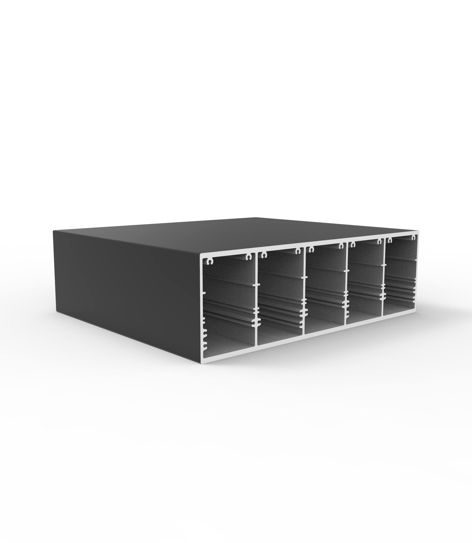
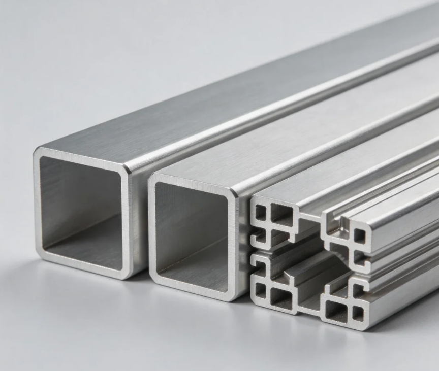
These frames often use asymmetrical multi-chamber profiles that combine mounting flanges, gasket channels and internal shear webs in one continuous bar. The outer chambers help absorb lateral impact forces, while stepped inner ledges can support a cooling plate or lower cover. Because several features share one profile, the design can need fewer fasteners and can simplify sealing along the pack perimeter.
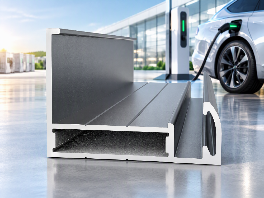
Side-pole impact testing is among the toughest hurdles in electric vehicle development, since a frontal crash can rely on a long crumple zone to absorb energy while a side impact against a narrow pole leaves very little structure between the pole and the battery modules. That difference in available crush distance is part of why rocker and side-sill design receives so much engineering attention in battery-electric platforms.
Extruded rocker panels and bumper crash boxes address this through controlled plastic deformation. A well-designed hollow section can fold progressively under load instead of snapping. Internal partition ribs divide the profile into smaller cells, and this compartmentalised geometry can influence how the walls fold and how much energy a given mass of metal absorbs. The actual outcome still depends on the alloy, temper, wall thickness and the specific load case, so each design needs component-level crash validation rather than an assumption drawn from the rib pattern alone.
Beyond the battery tray, extruded beams serve as longitudinal chassis rails, brace members and interior seat frameworks. Our product data lists chassis and subframe assemblies, body frames and vehicle interior frameworks among the typical uses. Thin-walled hollow sections in upper body structures also help keep mass low and high in the vehicle from growing.
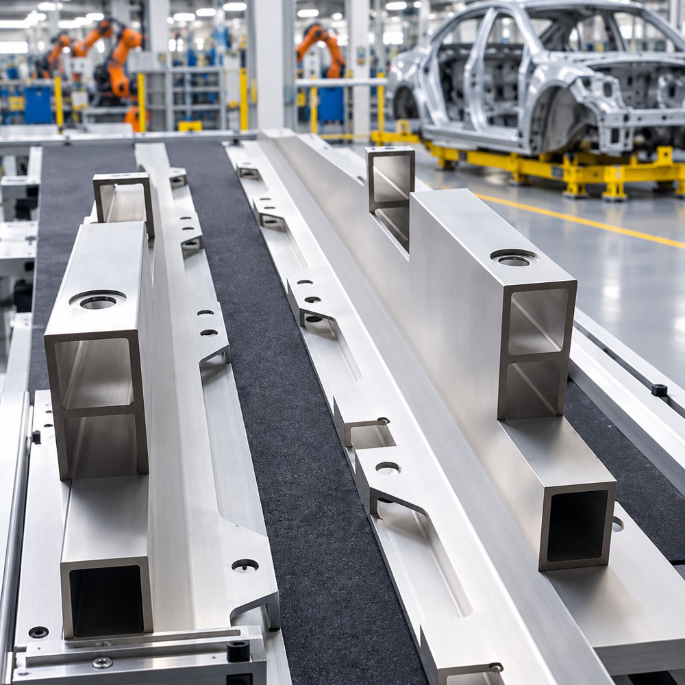
After extrusion, these profiles can move to multi-axis CNC machining centres and become ready-to-assemble components. Milling creates recessed mounting pads, bushing bores and threaded holes in a controlled sequence that follows the part’s final assembly requirements rather than a generic template. Because the extrusion already carries the correct wall thickness and internal webs along its length, the machining step mainly adds local features instead of reshaping the whole section. Done well, this route offers repeatable dimensions across high-volume production runs, which matters when hundreds of identical subframes need to fit the same robotic assembly line without manual adjustment.
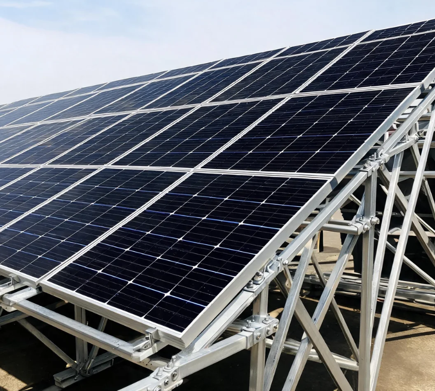
The same profile technology extends outside the vehicle plant. Our application list includes solar mounting structures and renewable energy installations. Solar carports, charging canopies and ground-mounted photovoltaic arrays all depend on aluminium racking that is light enough to handle and durable enough to stay outdoors through repeated seasons of wind, rain and temperature swings.
Extruded rails can include T-slots and retention grooves, which let installers clamp panels onto the rail without drilling it in the field. That detail helps preserve the surface coating, since every drilled hole through a protective finish is a potential entry point for moisture. It also shortens installation work, since the profile geometry already holds the hardware in place before fasteners are tightened.

Choosing an aluminium extrusion for electric vehicles is rarely a matter of picking the hardest alloy on a datasheet. Most structural extrusions come from the 6000 series, which uses magnesium and silicon as its main alloying elements. The family balances strength, weldability and the ability to flow through complex dies.
The table below compares the alloys and tempers in our product range. The strength figures are approximate and vary by wall thickness, the governing standard and the production batch. For 6060-T6 in particular, published minimum values for extruded sections differ by wall thickness, so treat any single figure as indicative only and confirm the applicable value against the relevant standard and the supplier’s data for the actual section before specifying it.
| Alloy & Temper | Yield Strength | Ultimate Tensile Strength | Extrudability & Cross-Section Complexity | Typical EV & New Energy Applications |
|---|---|---|---|---|
| 6061-T6 | ~276 MPa (approx., varies by standard and section) | ~310 MPa (approx., varies by standard and section) | Moderate; suited to thicker walls and simpler hollow shapes | Chassis subframes, longitudinal load beams, reinforcement bars |
| 6063-T6 | ~214 MPa (approx., varies by standard and section) | ~241 MPa (approx., varies by standard and section) | High; suits intricate multi-chamber profiles and smooth finishes | Battery enclosure side rails, interior framing, solar mounting rails |
| 6063-T5 | ~145 MPa (approx., varies by standard and section) | ~186 MPa (approx., varies by standard and section) | High; suits thin-walled sections | Light structural brackets, trim, cooling channels |
| 6060-T6 | Varies by wall thickness; confirm against the governing standard and supplier data for the specific section | Varies by wall thickness; confirm against the governing standard and supplier data for the specific section | High; suits thin walls and fine detail | Rocker inserts, crash boxes, cable trays |
When a component must resist suspension loads or high bending moments, 6061-T6 is a common structural choice. Its typical yield strength sits around 276 MPa, with an ultimate tensile strength near 310 MPa, though exact figures depend on the section and governing standard. That is a strong result for a metal that weighs about a third as much as steel.
The trade-off is flow resistance. The higher alloy content makes 6061 harder to push through dies with very thin walls or many small cavities, which raises press load and die wear. For this reason, engineers tend to specify 6061-T6 for thicker-walled beams, subframe mounts and CNC-machined brackets, where strength outweighs cross-sectional intricacy.
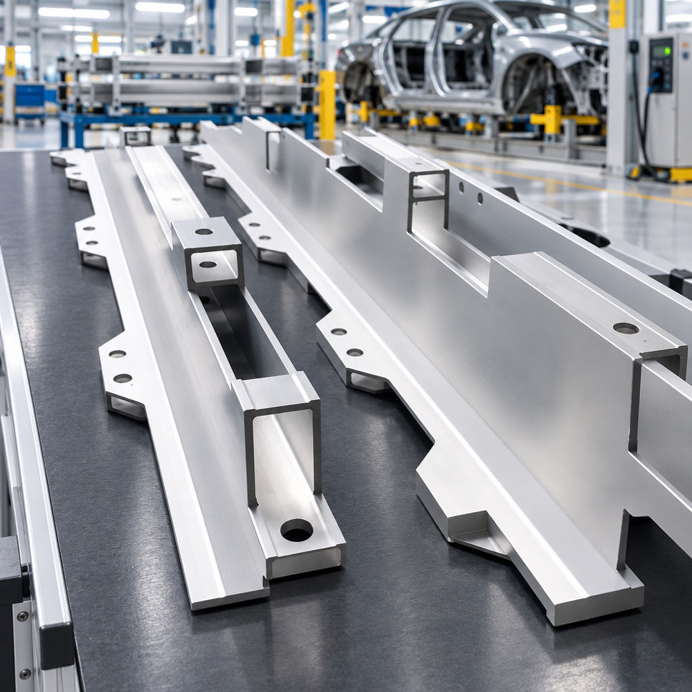
What happens when a battery tray design calls for a four-chamber profile with integrated seal grooves and thin internal webs? Here 6063-T5/T6 and 6060-T6 are often easier to work with. These alloys flow smoothly through intricate dies, which helps manufacturers hold wall-thickness tolerances across wide, asymmetrical sections.
These alloys are reasonable candidates for crush-oriented parts such as rocker inserts and crash boxes, but lower nominal strength does not by itself determine crash behaviour. How a section folds or fails under impact depends on the alloy and temper together with the cross-sectional geometry and the specific load case. Each design still needs component-level testing before release, regardless of which alloy is chosen.
An electric vehicle battery pack rides just above wet asphalt, gravel and winter de-icing salts. Aluminium forms a thin protective oxide film in open air. Whether an underbody part needs additional surface treatment beyond that natural film depends on its location, the joint design around it and the environment it will see in service, rather than being a fixed requirement for every component.
Why is surface protection treated as a safety parameter in electric mobility? When salt-laden slush splashes onto a chassis joint, it acts as an electrolyte. If an aluminium battery housing bolts directly against steel or copper parts without proper isolation, galvanic corrosion can start at the contact interface.
Over years of service, pitting along a sealing flange can weaken the pack’s ingress protection. Moisture inside a high-voltage enclosure then becomes a risk for insulation faults. Where the service environment or dissimilar-metal joints warrant it, a suitable coating can help limit exposure to moisture and road salt, which is the protection our product data describes for rain, moisture and road salt spray. Corrosion protection in practice may also call for electrical isolation between dissimilar metals, sealing at joints and gaskets, and validation of the complete assembly rather than reliance on the coating alone.
Matching the surface treatment to the vehicle zone avoids unnecessary processing cost while protecting the part, since a profile that will be welded or hidden inside a sealed cavity has different needs than one exposed to weather. The options in our range work as follows:
Mill Finish: Supplied straight from the press and ageing oven with no secondary coating. It suits internal structural inserts, enclosed cavities and profiles that will be welded or machined before final protection.
Anodizing and Electrophoresis: Anodizing grows a dense oxide layer from the metal itself, while electrophoretic deposition applies a uniform organic film that reaches into recesses. Both can protect machined mounts and interior framing against humidity.
Powder Coating: Applied electrostatically and cured with heat, it forms a thick barrier that helps against stone chipping on rocker panels and underbody brackets.
Fluorocarbon Coating: A durable paint-type finish often chosen for weathering resistance, so it fits exterior trim, roof racks and outdoor solar charging structures.
Moving a custom profile from a 3D CAD model to serial production takes close coordination between structural engineers and die designers, since decisions made on screen determine whether the part extrudes cleanly or fights the press at every run. Overlooking extrusion limits in the early design stage often leads to warped profiles, die revisions and delayed launches, which is why experienced sourcing teams involve the extrusion supplier before the drawing is finalised rather than after tooling has already been cut.
When metal flows through a hollow extrusion die, thin sections tend to move slower than thick ones. Suppose a profile places a 10-millimetre mounting boss next to a 1.5-millimetre web. Uneven cooling after the press can then twist or bow the section, since the thicker mass retains heat longer than the thin web next to it and the two areas contract at different rates as the part cools.
To limit distortion, keep wall thickness as uniform as the load paths allow and use generous fillet radii at web junctions instead of sharp internal corners. Rounding sharp interior corners reduces stress concentration in service and also eases the metal flow through the die, which can extend tool life and reduce the scrap rate during the early stages of a production run.
Sourcing teams can streamline custom profile development with a structured five-step workflow:
Define the load path and failure mode: Decide whether the part is stiffness-critical, such as a chassis subframe that may suit 6061-T6, or crush-critical, such as a battery side rail or crash box that may suit 6060-T6 or 6063-T6, subject to component-level validation.
Consolidate adjacent stamped parts: Review nearby brackets, seal channels and backing plates to see whether they can merge into one multi-chamber die.
Specify welding and surface preparation: Identify which faces need bare metal for welding or grounding, then assign mill finish, anodizing, powder coating or fluorocarbon protection to the rest.
Validate lead times and minimum order quantities: For early prototype builds, look for partners that accept small trial runs. Our listed terms are an MOQ of 250 to 500 kilograms per section and delivery in 10 to 20 days.
Verify capacity for serial ramp-up: Once validation is complete, confirm the supplier can scale. Xinhe Aluminium, established in 1998, integrates R&D, manufacturing and sales for customers in more than 50 countries, with over 5,000 profile products, an annual capacity of 200,000 tons and custom size, alloy and surface treatment options.
High-pressure die-castings can contain internal gas porosity, and the degree to which this affects ductility depends on the casting process and the quality control applied during production. Extruded wrought profiles are generally better suited to long parts with a constant cross-section, since the same die can produce a continuous rail without the tooling complexity of a large casting. Extrusion does not automatically guarantee superior crash performance, however. Whether a given section folds progressively or absorbs energy reliably still depends on the alloy, temper, wall thickness and geometry, and needs to be confirmed through component-level crash testing rather than assumed from the process alone.
Alloy 6061-T6 offers higher yield and tensile strength, so it suits rigid chassis beams and brackets where resisting bending loads matters most. Alloy 6063-T6 is easier to extrude into thin-walled, complex shapes and gives a smoother surface finish, which makes it a practical choice for multi-chamber battery rails and interior framing. Neither alloy is automatically the better choice across every application. Final selection should rest on the specific load case, the section geometry required by the design and the results of part-level testing, since published strength values are approximate and vary with wall thickness and standard.
For exposed underbody zones, powder coating, or electrophoresis combined with anodizing, gives a protective barrier against chipping and de-icing salts. If the rails will be welded during tray assembly, profiles are often supplied in mill finish and coated afterwards, since coatings can interfere with weld quality if applied beforehand. The right sequence depends on your assembly process, including which faces need to stay bare for welding or grounding and which faces are fully exposed to road spray once the vehicle is in service.
For custom cross-sections, our listed MOQ is 250 to 500 kilograms per section, which covers billet heating and die setup costs that make very small runs impractical. Delivery time is 10 to 20 days under standard conditions. Die complexity, the number of surface treatment steps and the need for secondary machining can all influence the actual schedule, so it is worth confirming these details against the specific profile design before committing to a launch timeline.
Electric vehicle design rewards engineers who treat structural mass as an energy budget. Every kilogram removed from a frame or battery housing can mean longer range, a smaller pack or sharper handling. Reaching that result takes more than catalog shapes. It means shaping load paths around the way 6000-series alloys actually flow, form and fail, and confirming that behaviour through testing rather than assumption.
Whether your team is validating a crash-absorbing rocker insert, machining a rigid subframe or scaling up a multi-hollow battery tray, the choice of aluminium extrusion for electric vehicles affects both crash performance and manufacturing cost. Pairing sound cross-sectional geometry with a suitable surface treatment and well-specified custom aluminium extrusion profiles for electric vehicles gives manufacturers a practical path to lighter new energy platforms.
Aluminium Door Profiles: An Engineering and Sourcing Guide for Modern Architectural Framing
What evidence is needed to claim Awing window seal failure under warranty?
How do I confirm Awing window drawings before production begins?
Can a Shutter prototype confirm both light control and ventilation performance?

Aluminium Extrusion Profiles for Solar Panels: Engineering and Sourcing Guide
The Definitive Guide to Aluminium Extrusion Profiles: Engineering Principles, Modular Systems, and P
Could smart Casement windows become a practical alternative to standard models?
Is it practical to develop a private-label Sliding window for my brand?
What spare parts should I stock for Floding door after-sales support?
Architectural and Industrial Aluminium Angle Profile Guide: Structural Sizing, Alloy Selection, and
How can I prevent my Casement window color formula from being reused?
What coating compliance evidence should I request for Decorative profile?
What information helps a factory understand my Sliding door customization needs?
Are new Shutter materials improving durability while reducing total project cost?
What extra charges should I ask about when buying Casement doors?
What files do I need to provide for a custom Decorative profile?
Should I hold the final Shutter payment until an independent inspection passes?
Are Decorative profile tooling fees normally refundable after reaching volume targets?
What defective-rate threshold should trigger compensation for Casement windows?
How can I tell whether an Architecture profile seller owns a real factory?
Can Shutter slat shapes be customized without creating long tooling delays?
Can a remote audit reliably confirm Sliding window quality controls?
How do I confirm an Architecture profile meets the required wall loads?
Can missing Casement window test reports delay customs clearance or installation?
How should I send CAD details for a custom Casement door design?
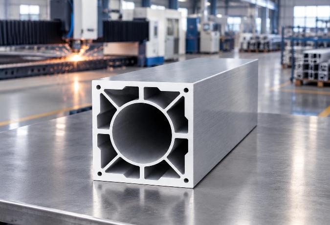
Choosing Industrial Aluminium Profiles for Laser Cutting Machines: A Technical Guide
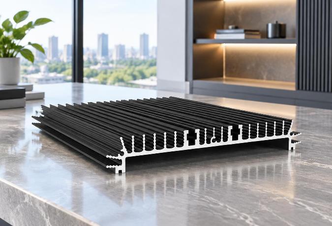
How LED Aluminium Profile Heatsinks Manage Thermal Challenges in High-Performance Lighting
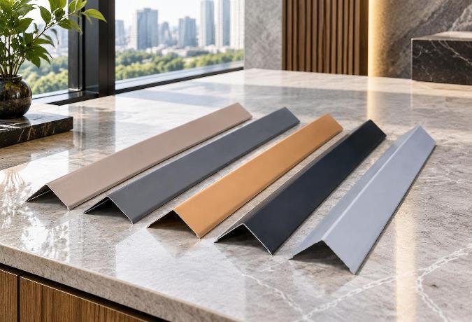
Architectural Aluminium Profiles: Choosing the Right Angle Design for Framing and Trim
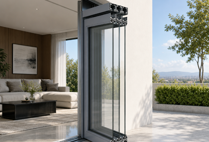
Choosing the Right Aluminium Door Profiles for Narrow-Frame Sliding Systems
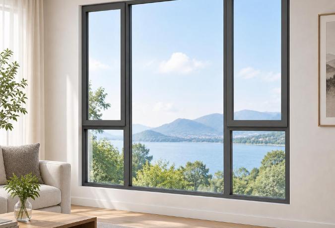
Aluminium Window Profiles: Engineering Durable Facades for Modern Buildings
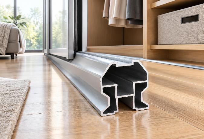
Aluminium Wardrobe Profiles: A Practical Guide to Frames, Tracks, and Finishes
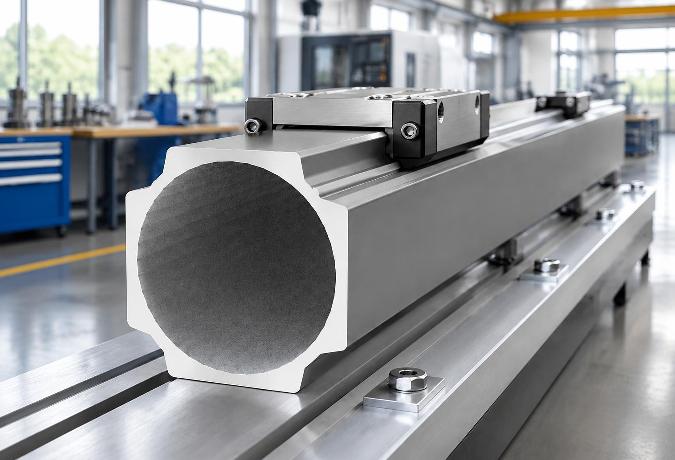
Choosing the Right Aluminium Linear Rail Profile for Motion Systems
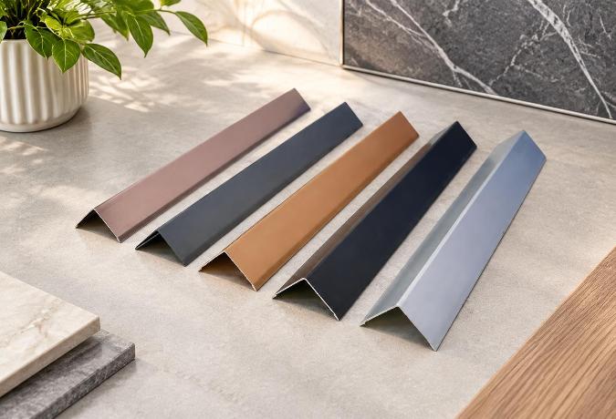
Anodized Aluminium Profiles: Material Selection and Practical Applications in Modern Design
Aluminium Decorative Profiles: Design, Installation, and Interior Applications
Aluminium Profiles for Automation: A Practical Guide to Modular Frame Design
Aluminium Extrusion for Furniture: Structural Logic Behind Lightweight Precision
Aluminium Thermal Break Profiles: Design Principles and Practical Applications
How do suppliers normally handle Sliding door installation problems overseas?
Choosing the Right Aluminium Balustrade Profiles for Your Project
Aluminium Louver Profiles: Light Control and Ventilation in Modern Architecture
Aluminium Curtain Wall Profiles: Structural Design and Performance in Modern Architecture
Aluminium Trim Profiles: Bridging Aesthetics and Performance in Modern Interior Design
How do I verify Casement window production capacity before signing a contract?
Powder Coated Aluminium Profiles: Durability and Design in Modern Applications
How Aluminium Heatsink Profiles Keep Electronics From Cooking Themselves
How do FOB and CIF change my risks when importing Sliding doors?
What support should I receive if Architecture profile dimensions are wrong?
Inside an Aluminium Profile Factory: How Angle Profiles Are Made and Chosen
What is a realistic MOQ for a first Sliding window trial order?
Which factory records should I review before buying Industrial profile?
Aluminium Extrusion for Machinery: Choosing the Right Profile for Industrial Equipment
Aluminium Extrusion for LED Lighting: Choosing the Right Heatsink Profile
Can a Floding door supplier protect my private design from competitors?
Which Industrial profile tolerances affect assembly accuracy and finished quality?
Can trade credit insurance cover my Architecture profile purchase risk?
Custom Aluminium Extrusion Profiles: Engineering Precision into Industrial Motion Systems
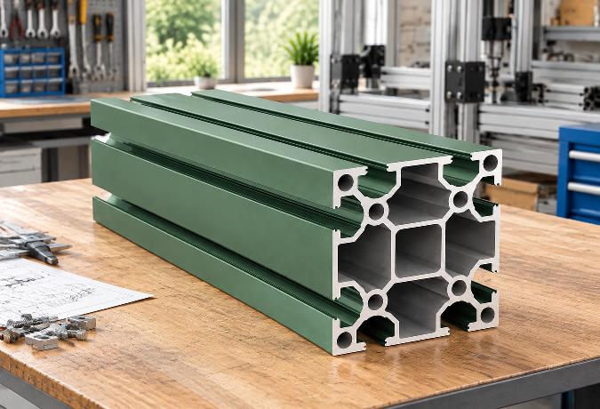
T-Slot Aluminium Extrusion: Structural Framework Design Without Welding
Which recycled-content records are credible for Sliding window procurement?
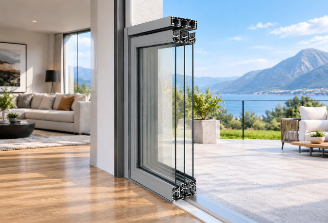
Aluminium Sliding Door Profiles: A Practical Guide to Frame Design and Performance
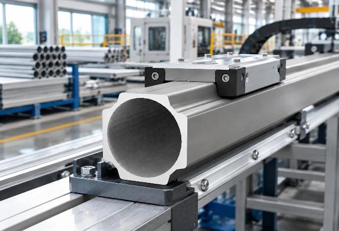
How Aluminium Extrusion Manufacturers in China Support Linear Motion Systems
What contract clauses protect my money if Casement door quality is unacceptable?
How do I confirm Sliding door testing equipment is calibrated and current?
Should I visit an Architecture profile plant before placing a large order?
Which compliance tests should a Floding door pass before international shipment?
How do I compare Decorative profile color samples under different lighting?
What payment and price terms make sense for a small Casement window order?
What lead time should I allow for a seasonal Floding door order?
How can I compare Floding door alternatives when supply costs suddenly rise?
Which new Sliding door technologies can lower maintenance costs over time?
How are recycled materials changing the future cost of Floding doors?
How long should a custom Casement door sample normally take to prepare?
What gap between a Sliding window sample and bulk order is acceptable?
Which Decorative profile finishes are becoming more sustainable and cost-effective?
What logistics fees should be listed separately in a Sliding window quote?
How might volatile aluminum prices affect future Sliding window sourcing?
Which audit questions reveal labor risks at a Casement door factory?
Can Decorative profile suppliers provide fast remote guidance for finish defects?
What should a Shutter sample include so I can assess production quality?
Do Sliding door materials need traceability records for customs clearance?
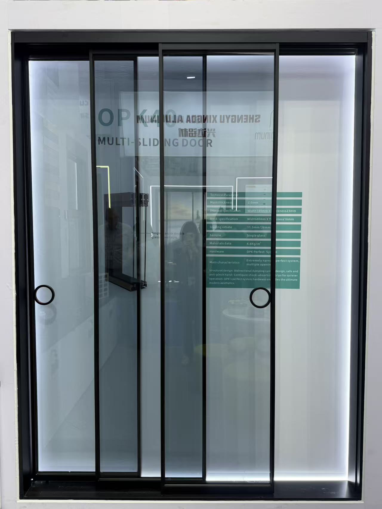
What environmental declarations are useful when importing Architecture profile?
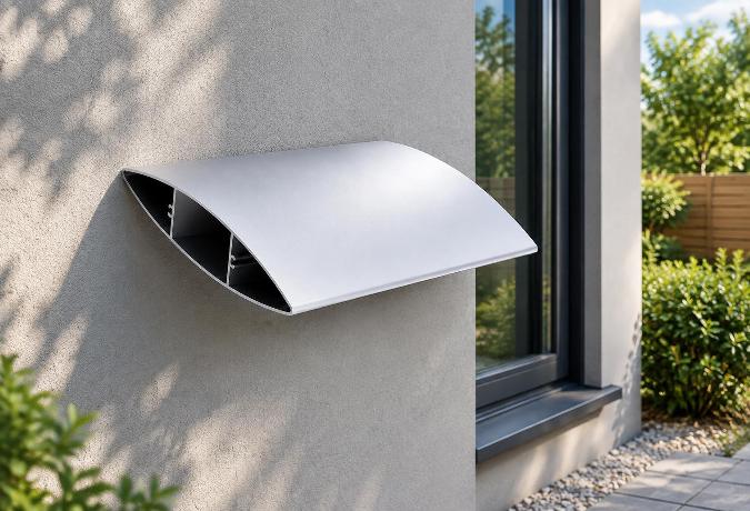
Why Blade Geometry Determines Whether Aluminium Louvers Actually Work
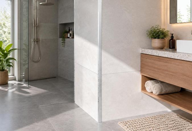
Engineering an Aluminium Angle Profile: Structural Mechanics and Application Realities
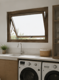
What usually drives Architecture profile costs more, alloy or surface treatment?
Why the One-Piece Molding on Aluminium Trim Profiles Matters More Than the Finish
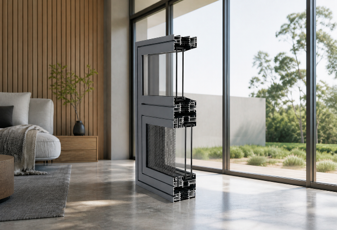
Why the Thermal Break Cavity Matters More Than Frame Thickness in Aluminium Framed Windows and Doors
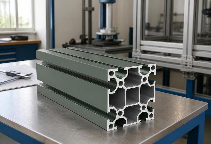
The T-Slot Groove Geometry That Makes Aluminium Framing Weld-Free
Why the One-Piece Molding on Aluminium Trim Profiles Matters More Than the Finish
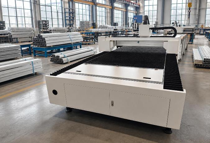
Structural Dynamics of Industrial Aluminium Profiles in Laser Cutting Gantries
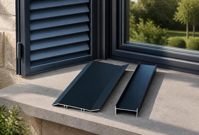
The Engineering Mechanics Behind High-Performance Aluminium Shutters
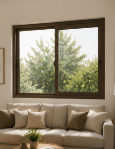
What factory documents should I request for a Floding door supplier review?
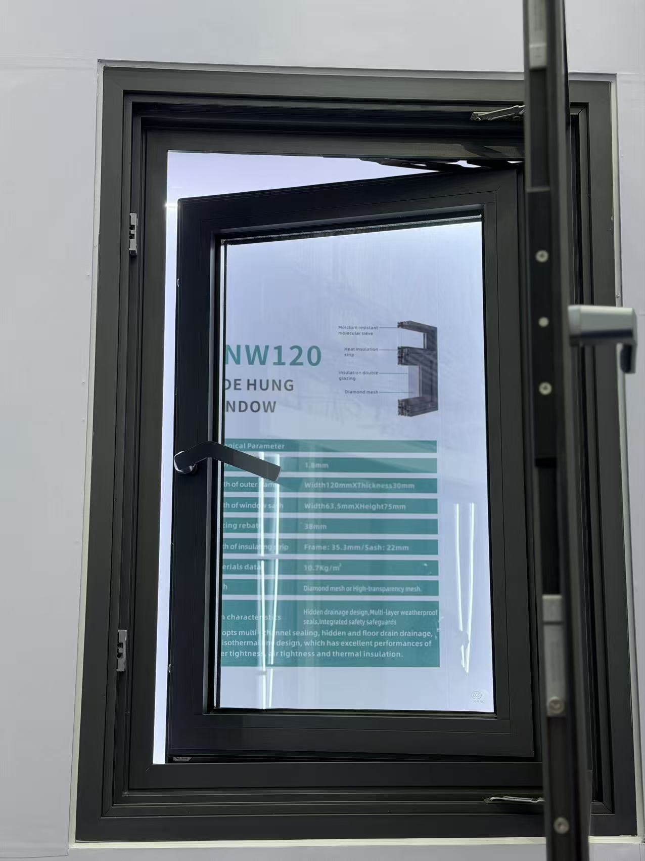
Which delivery term gives me better control over Decorative profile freight costs?
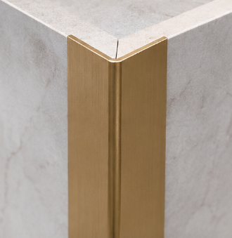
What low-carbon Awing window materials are gaining wider market acceptance?
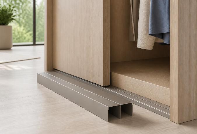
Why Sliding Door Track Geometry Determines Wardrobe Longevity
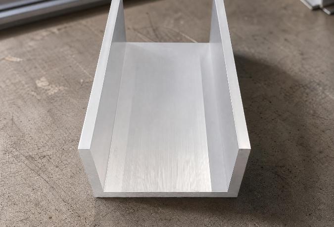
Engineering Mechanics and Surface Dynamics of Aluminium Channel Profiles
Understanding Aluminium Round Tube Specifications for Structural Engineering
Why the 90-Degree Angle in Standard Aluminium Profiles Determines Structural Reliability
How can I ensure a Floding door sample matches the planned mass production?
Why Mullion Thickness Determines How Much Glass an Aluminium Curtain Wall Can Actually Hold
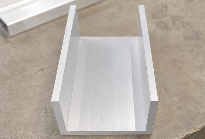
Engineering Dimensional Stability in Aluminium Extrusions for Channel Profiles
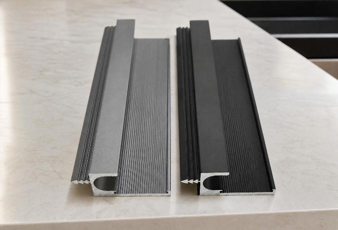
Engineering the Structural Framework: The Mechanics of Aluminium Profiles for Kitchen Cabinets
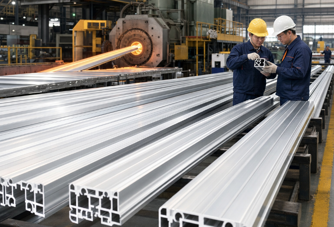
Choosing an Aluminium Profile Supplier: What Actually Separates the Reliable Ones from the Rest
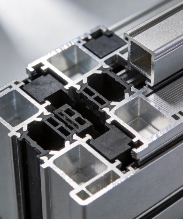
Can Awing window orders ship in batches to avoid project delays?
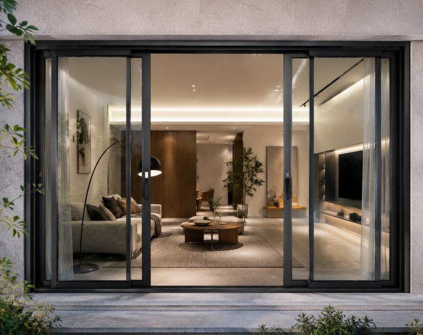
What response time should I expect for Awing window warranty claims?
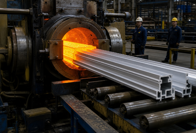
Navigating the Supply Chain: Evaluating an Aluminium Profile Manufacturer for B2B Procurement
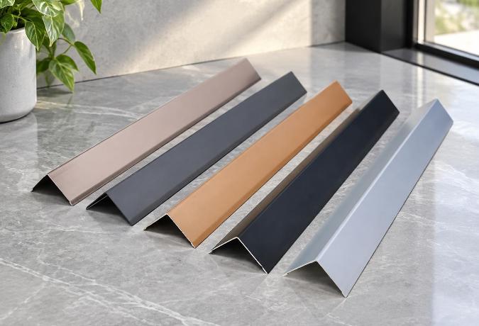
Engineering Structural Integrity Through Precision L-Shaped Aluminium Profiles
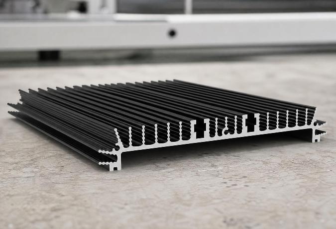
Thermal Dynamics in High-Power Electronics: Engineering Aluminium Heatsink Profiles
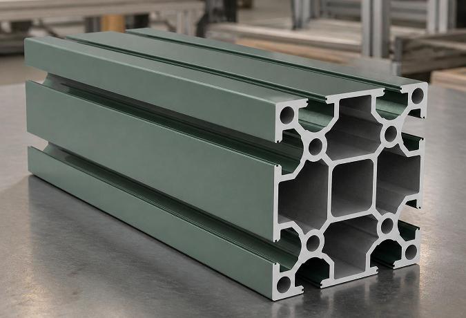
Why the T-Slot Design Determines the Real Strength of Structural Aluminium Extrusions
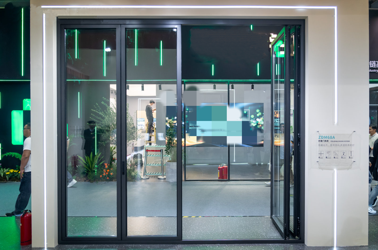
How long should replacement Sliding window parts remain available after purchase?
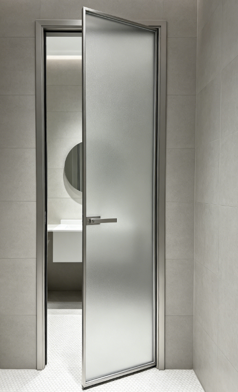
Should I expect volume discounts when reordering the same Sliding window model?
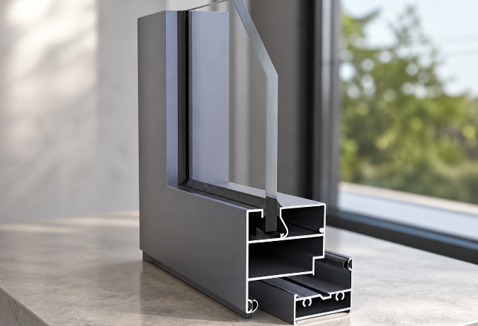
The Multi-Strip Sealing Structure Inside Aluminium Windows and Doors
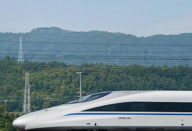
Engineering Lightweight Rail Structures Through Extruded Aluminium Profiles
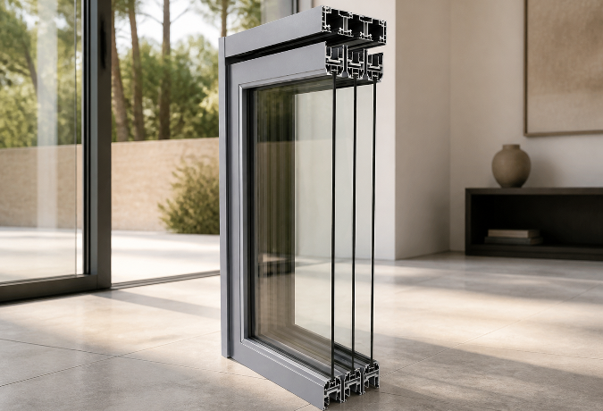
Why the Frame Width on an Aluminium Sliding Door Determines Your Room’s Light
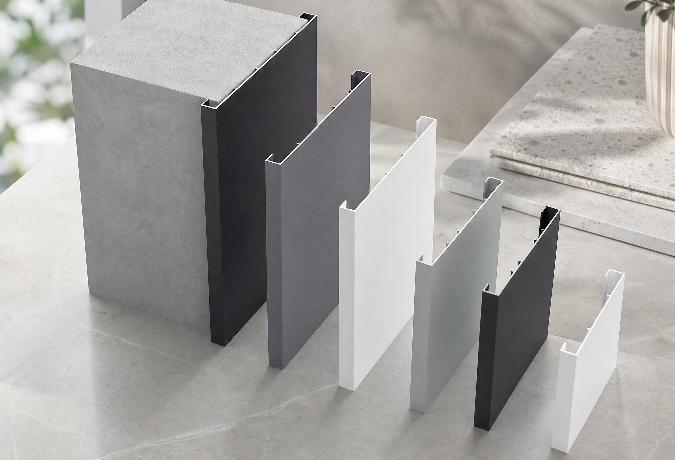
The Engineering Behind Decorative Aluminium Profiles: Alloys, Surface Treatments, and Edge Protectio
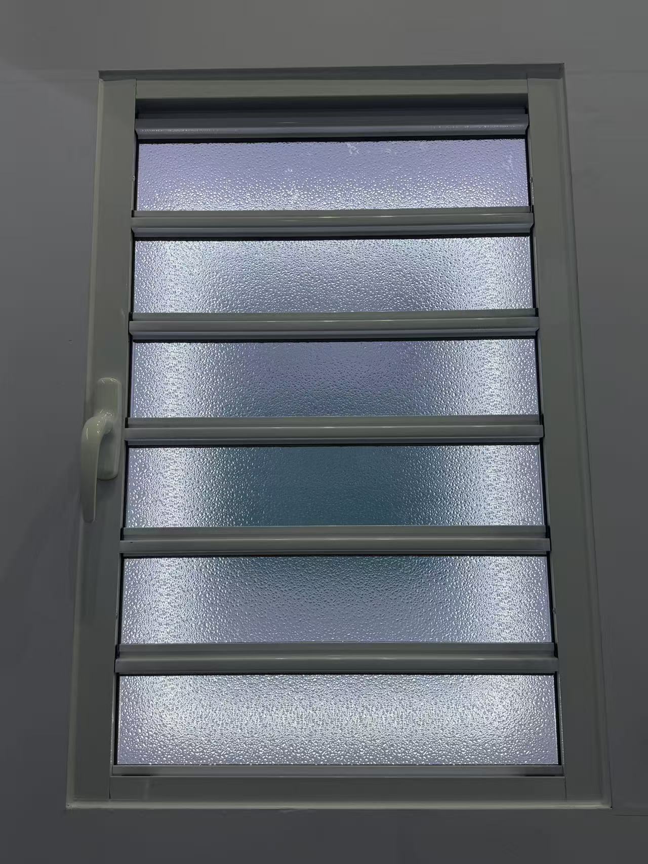
What alternative materials could make Casement doors more resilient and recyclable?
How can I compare Awing window quotes without missing hidden packing costs?
Decoding Structural Tolerances in Aluminium Extrusion Profiles for Channel Applications
Engineering an Aluminium Square Tube for Modern Structural Integrity
Engineering Tolerances and Alloy Mechanics in Extruded Aluminium Construction Profiles
The Engineering Mechanics Behind Aluminium Angle Profiles in Modern Construction
Can an Industrial profile be modified for my assembly without weakening it?
What warning signs suggest a Sliding door seller may disappear after payment?
What energy-efficient alternatives to Casement doors are worth comparing now?
Can a Casement window handle temperature changes without seal failure?
Who pays for unloading and destination handling under Casement door CIF terms?
Custom Aluminium Extrusion Profiles: The Engineering Mechanics of T-Slot Frameworks
Material Transitions and Geometric Stability in Decorative Aluminium Profiles
Can I negotiate a lower Sliding door MOQ for a showroom launch?
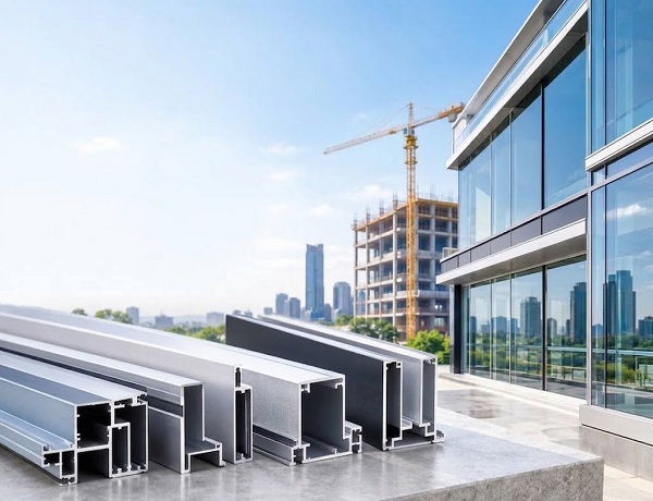
Key Advantages of Using Structural Aluminium Extrusion Profiles in Construction
What evidence shows an Awing window factory manages coating waste properly?
How can I protect my deposit when ordering custom Decorative profile?
How do I spot unusually low Industrial profile prices before committing funds?
How can I check that a Shutter supplier is not using unapproved subcontractors?
What contract terms protect my Casement door drawings and branding?
How can I compare Casement door insulation ratings before placing an order?
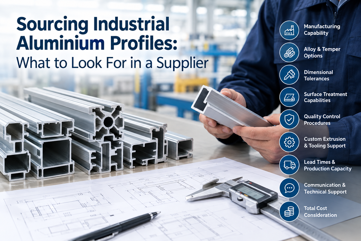
Sourcing Industrial Aluminium Profiles: What to Look For in a Supplier
How do I keep ownership of a custom Architecture profile extrusion die?
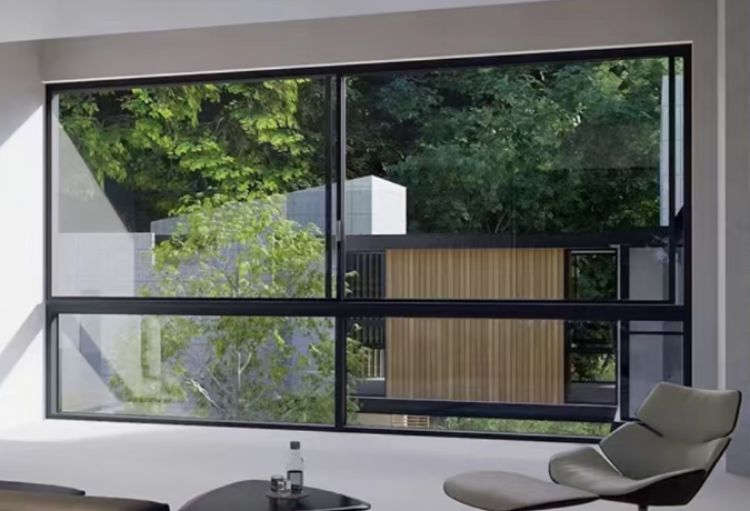
The Energy Efficiency Benefits of an Aluminium Frame Sliding Glass Window
How do I check Industrial profile alloy grades against the shipping documents?
What Casement window warranty period is reasonable for an overseas buyer?
How are defective Sliding window units usually replaced internationally?
How can I reduce breakage risks when shipping Casement windows overseas?
The Structural Mechanics Behind Decorative Aluminium Profiles
How Do Engineers Select Industrial Aluminium Profiles for High-Load Frameworks?
What payment structure reduces my risk on a first Industrial profile order?
Should I approve a Casement window sample before checking its hardware strength?
Structural Mechanics of Channel Extrusions in Architectural Aluminium Profiles
Engineering Mechanics of Aluminium Extrusion Profiles in Channel Systems
What functional tests should I perform on a Sliding door prototype?
What payment terms are fair when Decorative profile colors remain unconfirmed?
Is a letter of credit practical for a large Casement window shipment?
How should Industrial profile bundles be packed to prevent transit damage?
Which safety documents should I request for Awing window imports?
What shipping delays commonly affect Architecture profile orders during peak season?
How to Specify Extruded Aluminium Profiles: Costs, Alloys, and Tolerances
Is a Floding door suitable for a wide opening exposed to strong winds?
Structural Integrity in Modular Design: Engineering T-Slot Aluminium Extrusion Profiles
Resolving Corner Stress: The Engineering Mechanics Behind Aluminium Profiles in Architectural Framin
How do Floding door prices change with glass, hardware, and finish choices?
How can I prove Shutter defects remotely without returning every unit?
How can I shorten Awing window sampling without losing critical tests?
Does ordering mixed Shutter sizes usually change the unit price or MOQ?
How should Industrial profile warranty responsibility be shared after assembly?
How should I plan Shutter inventory when ocean freight schedules change?
How do escrow arrangements reduce risk for a new Floding door supplier?
What frame materials make a Sliding window last in harsh coastal weather?
How can I verify that a Shutter certificate matches the actual product?
Can automated Shutters replace manual systems without raising lifecycle costs?
How do I choose the right Casement window size for a windy building?
What should an ethical audit cover at a Decorative profile factory?
How should I document Industrial profile defects before disputing the final payment?
Are lightweight Industrial profile alloys reliable enough for demanding machinery?
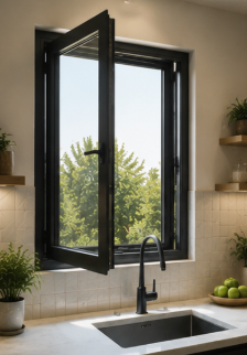
Are thermal-break casement windows becoming a better long-term choice than standard frames?
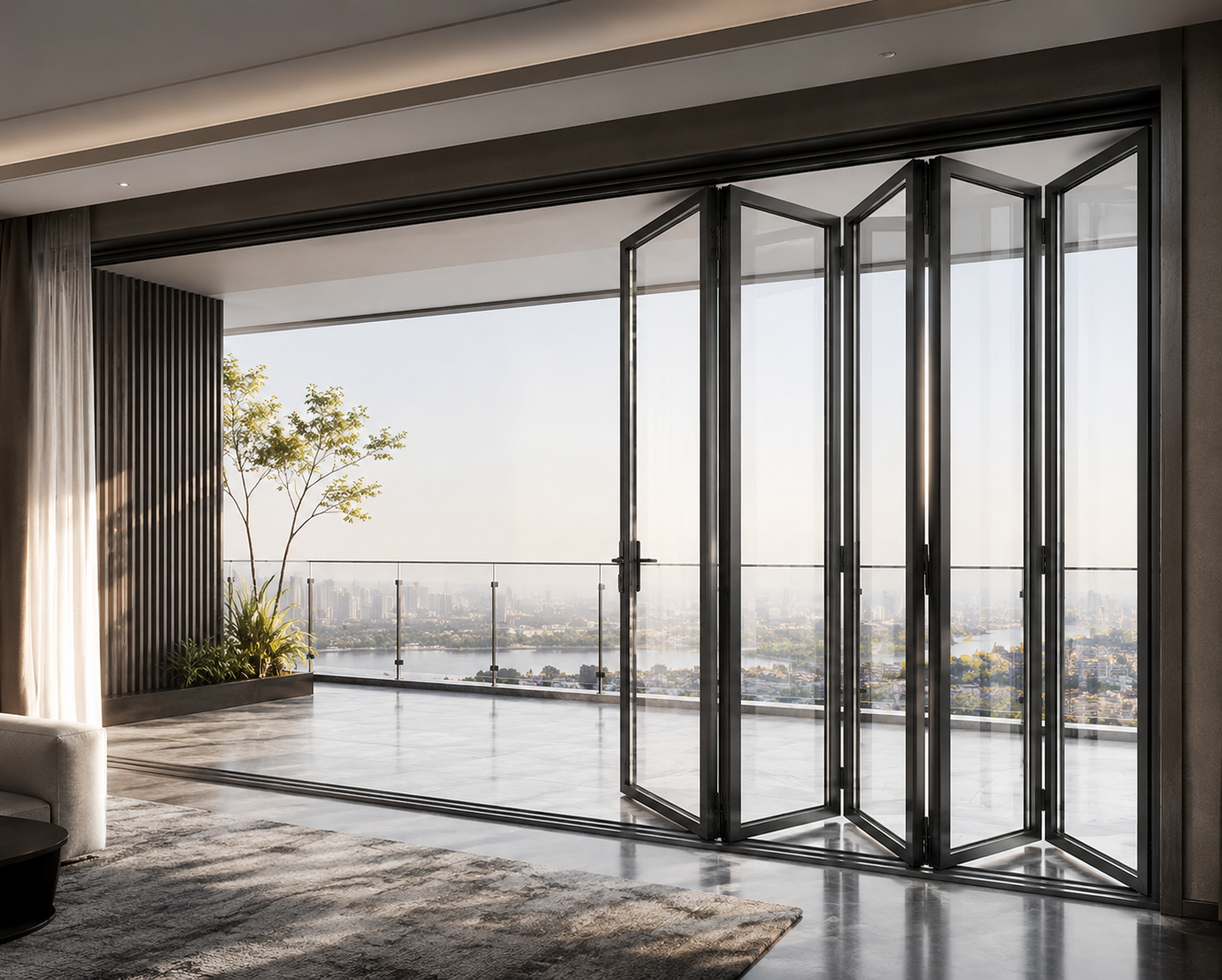
What is a realistic MOQ for custom sliding windows without pushing up unit cost?
What casement window specs should I compare for windy and rainy project sites?
Are there better material options for sliding windows if aluminum prices rise?
How do I ensure aluminum casement windows can handle extreme coastal winds?
What is the typical minimum order quantity for commercial sliding windows?
Are there energy-saving alternatives to sliding windows that reduce material and maintenance costs?
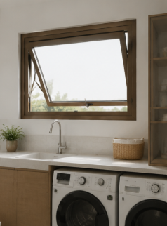
Are energy-efficient Awing windows a practical alternative for reducing long-term building costs?
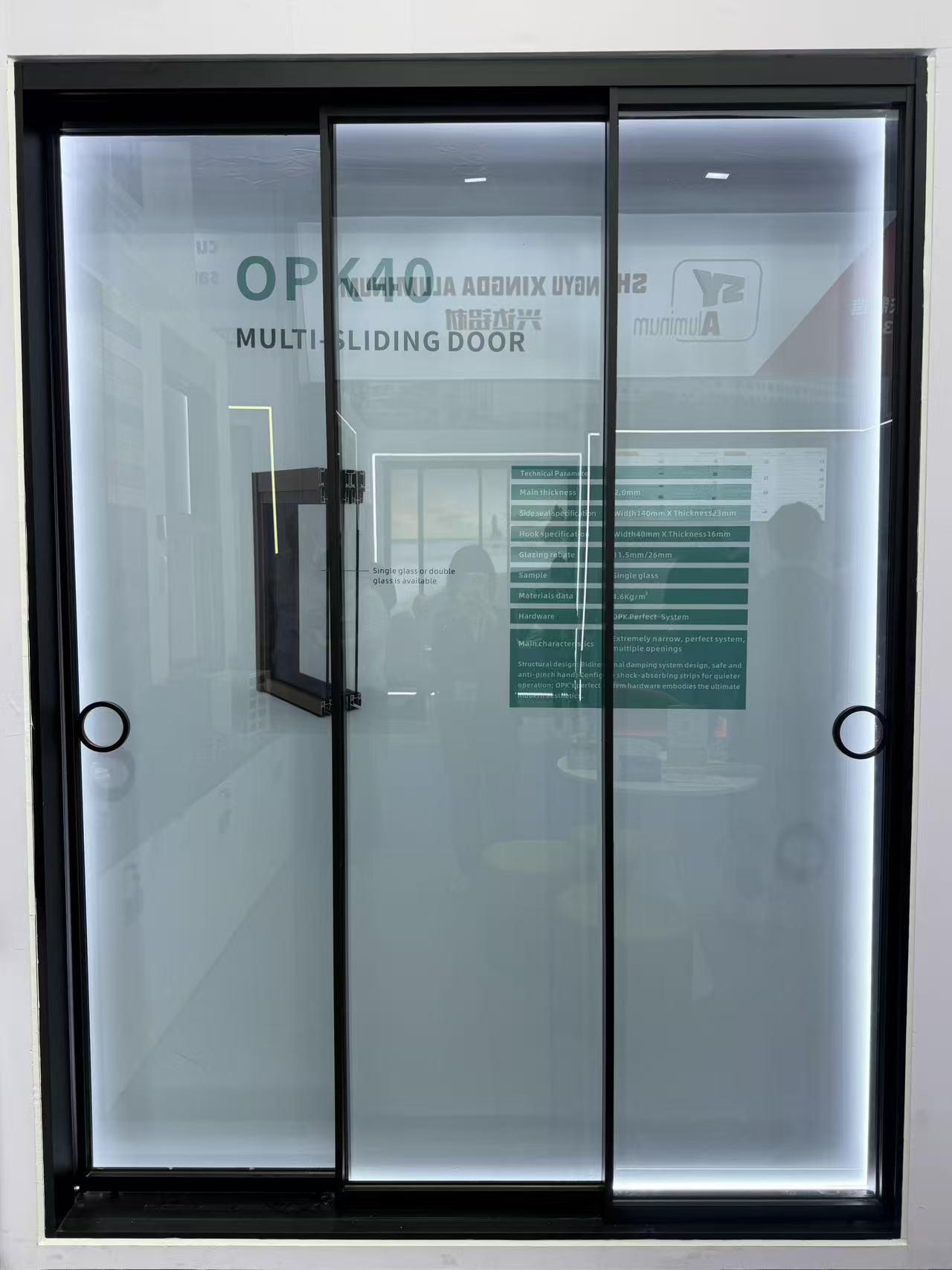
What alternatives to traditional sliding doors can lower costs without sacrificing durability?
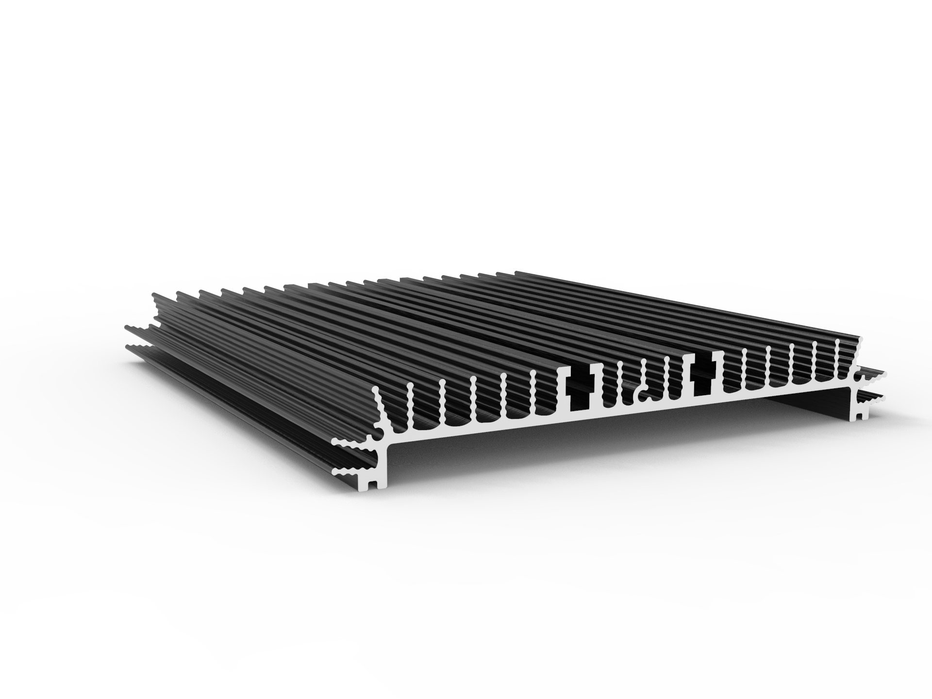
What alternatives to industrial profiles can reduce material costs without hurting strength?
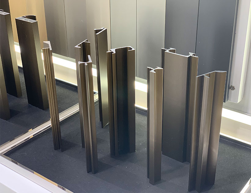
Extruded Aluminium Profiles: Flexible Manufacturing for Diverse Customer Needs
Why Aluminium Curtain Walls Are Popular in Modern Architecture
How do I choose a decorative profile that stays stable in humid or harsh environments?
How do I choose an architecture profile that stays stable in harsh outdoor conditions?
How can I compare Awing window specs to avoid poor performance in harsh weather?
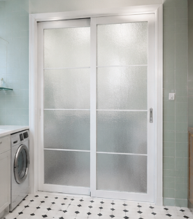
How can I compare Sliding door sizes and hardware ratings for harsh commercial environments?
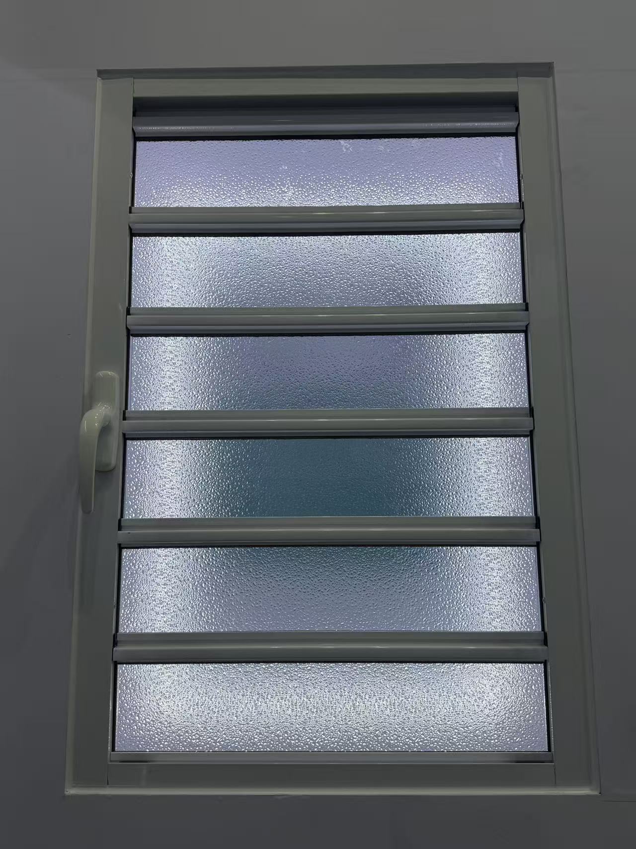
How do I choose the right shutter specifications for harsh climates without overpaying?
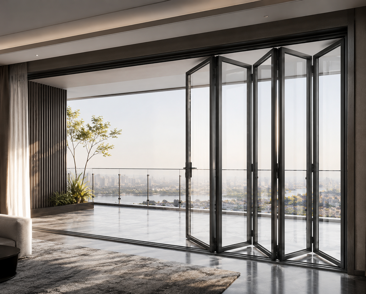
What eco-friendly alternatives to folding doors can cut costs without hurting durability?
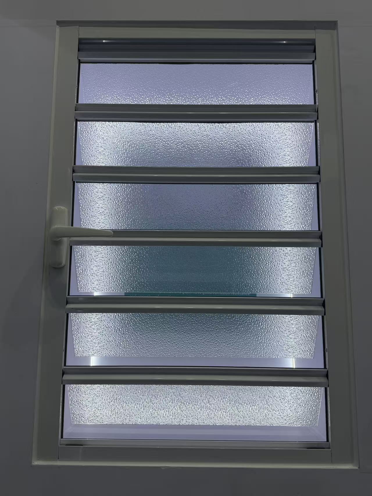
How do I choose the right shutter specifications for harsh weather without overpaying?
What eco-friendly casement door materials can lower costs without hurting durability?
What newer materials can replace industrial profiles without raising costs or supply risks?
How do I choose a decorative profile that stays stable in humid, high-traffic spaces?
What sustainable material alternatives can replace aluminum architecture profiles?
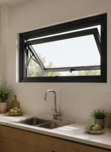
What should I check in Awing window specs to ensure reliable performance in harsh weather?
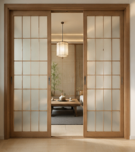
How can I compare Sliding door sizes and thermal ratings for harsh climates before buying?
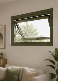
What newer materials can replace aluminum in awning windows without raising our costs?
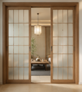
How do I choose the right Sliding door specs for smooth operation in harsh environments?
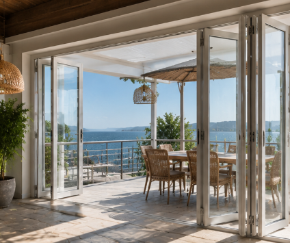
How do I choose a folding door that stays stable in harsh weather and heavy daily use?
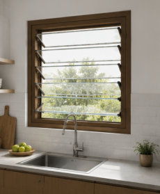
How can I choose the right shutter specifications for harsh weather and long-term use?
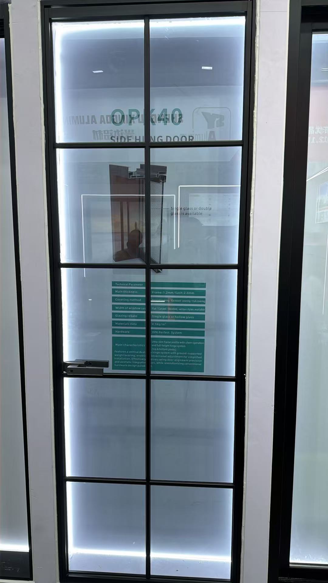
How do I compare casement door U-values, hardware, and weather sealing before buying?
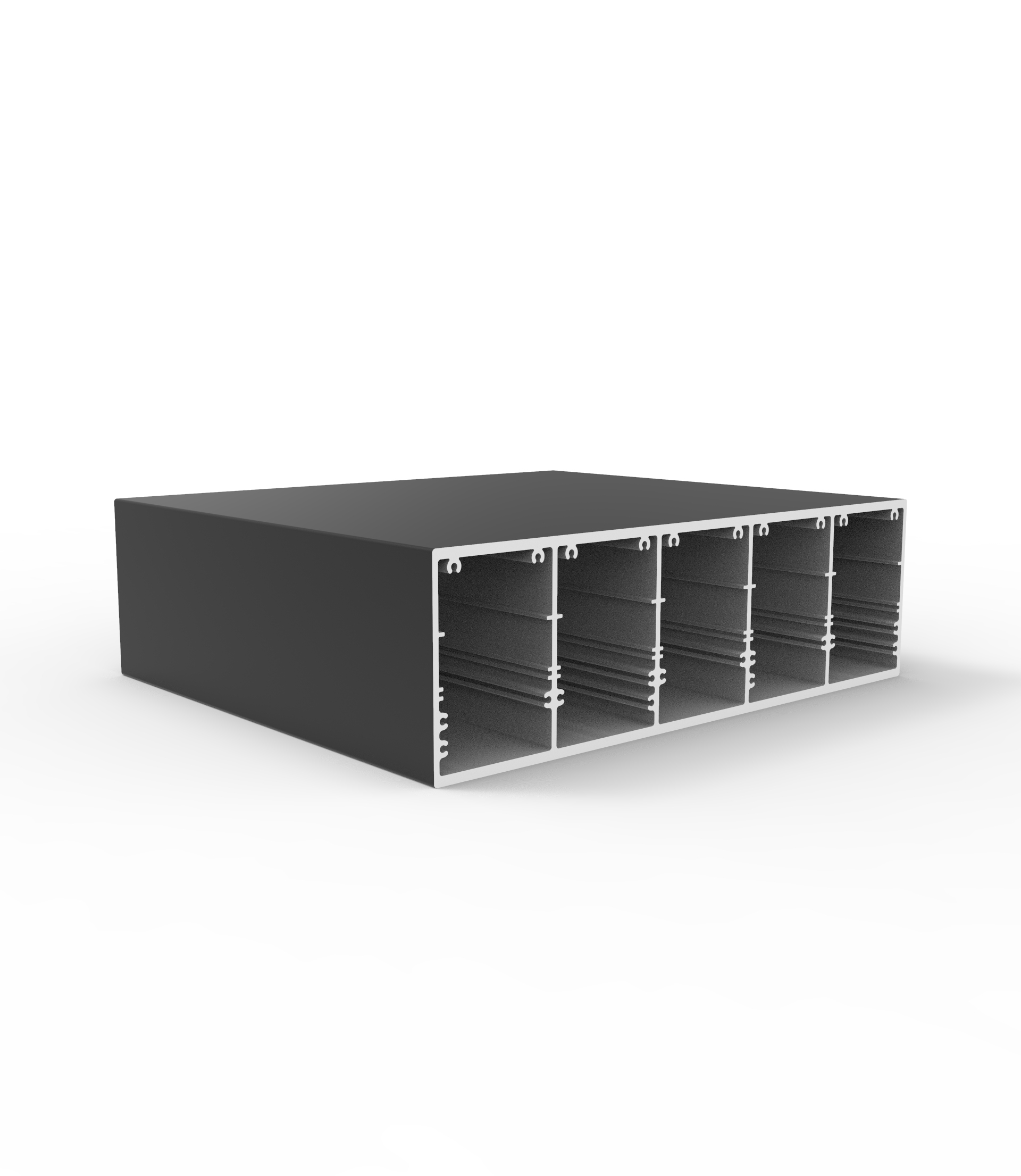
How do I choose the right industrial profile size for strength and load needs?
How do I choose the right shutter specifications for harsh weather and long-term commercial use?
How do I choose the right Casement door size and hardware for harsh weather?
What greener alternatives to decorative profile can cut costs without hurting durability?
What lower-cost, eco-friendly materials can replace decorative profiles?
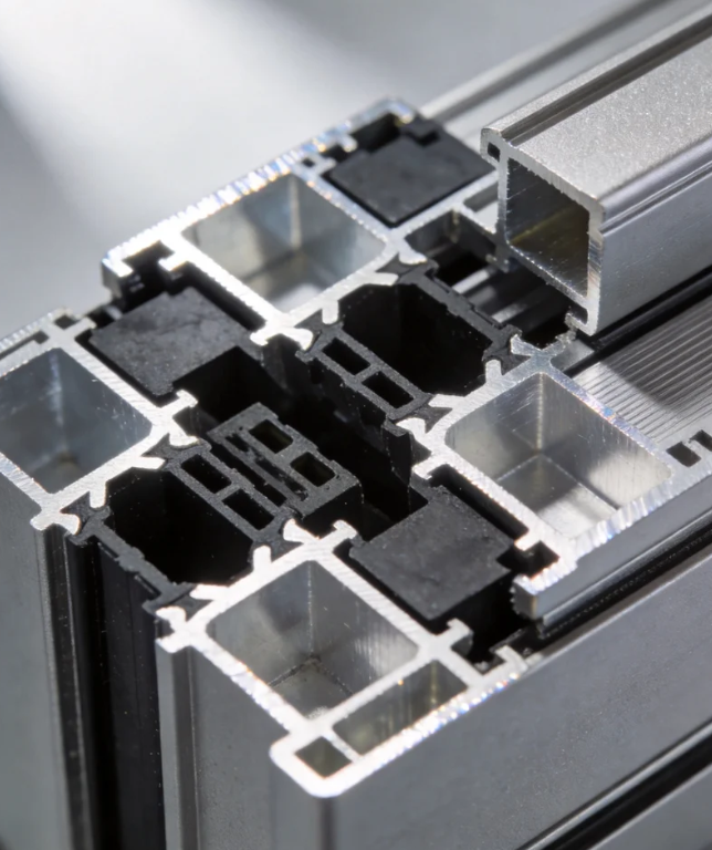
What lower-carbon alternatives to aluminum architecture profiles are practical for our project?
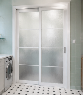
How can I compare sliding door systems for insulation, security, and long-term use?
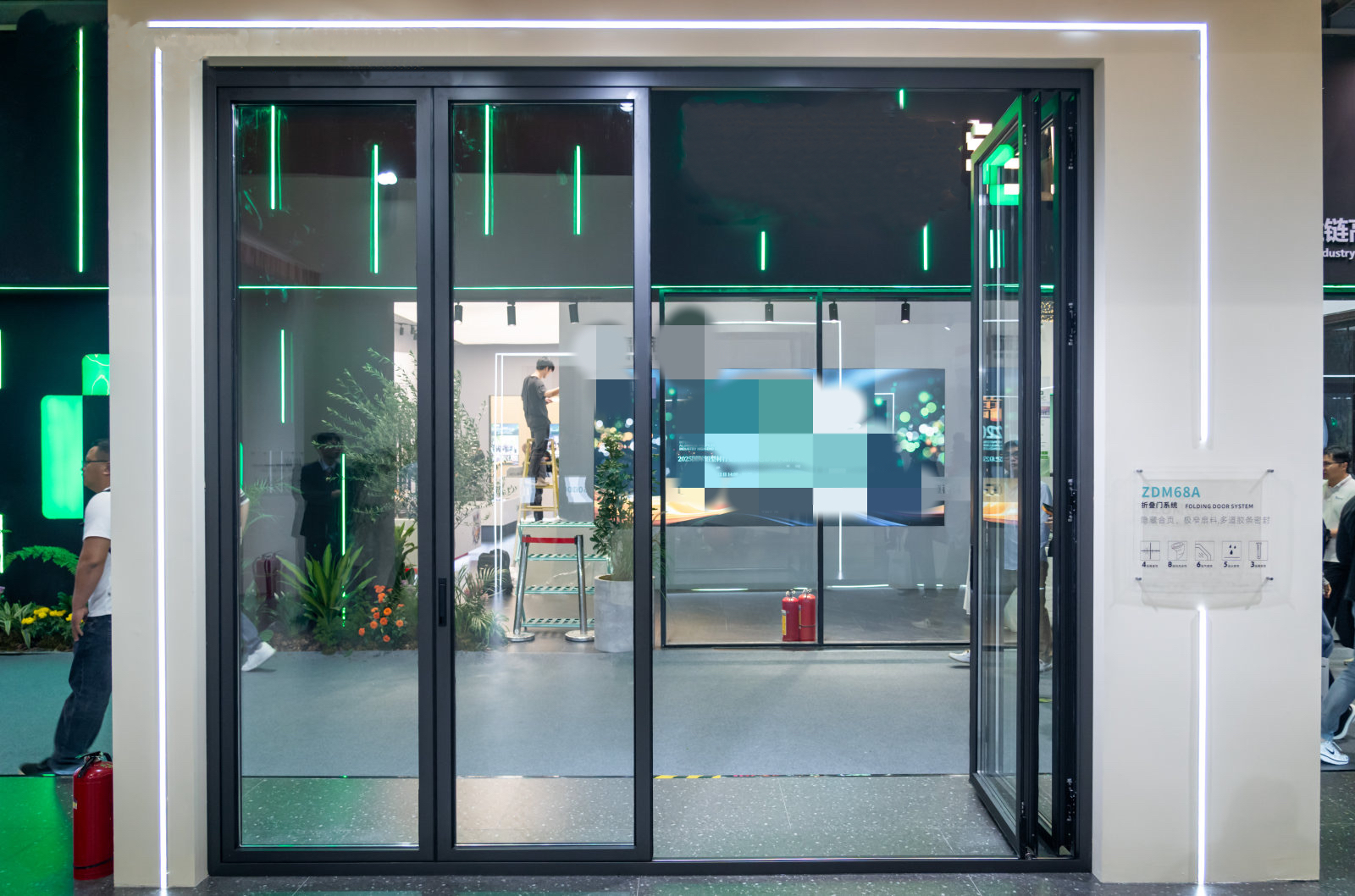
What is the standard production lead time for bulk orders of folding doors?
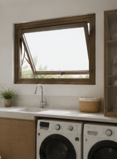
How do I choose the right Awing window size and glass specification for harsh weather?
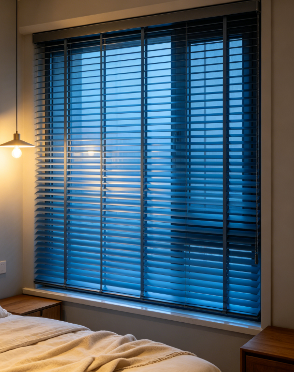
How can I test shutter samples so the final bulk order matches their quality and finish?
Can suppliers make custom double glass casement doors from my CAD drawings?
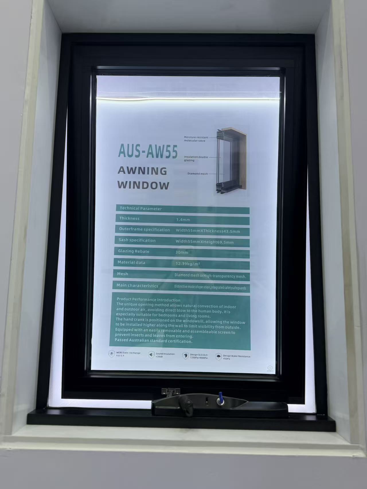
What safety certifications should I request when importing awning windows?
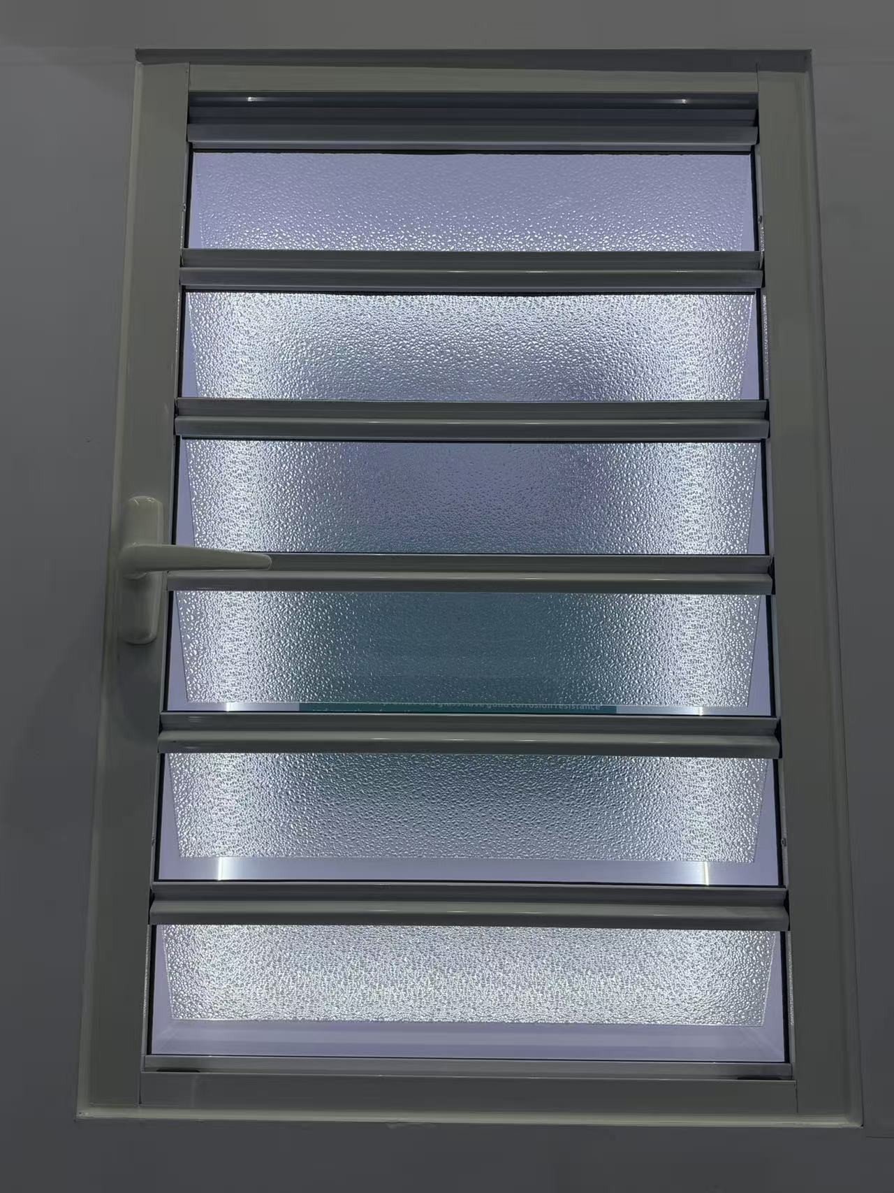
How long does it usually take a factory to make custom shutter samples?
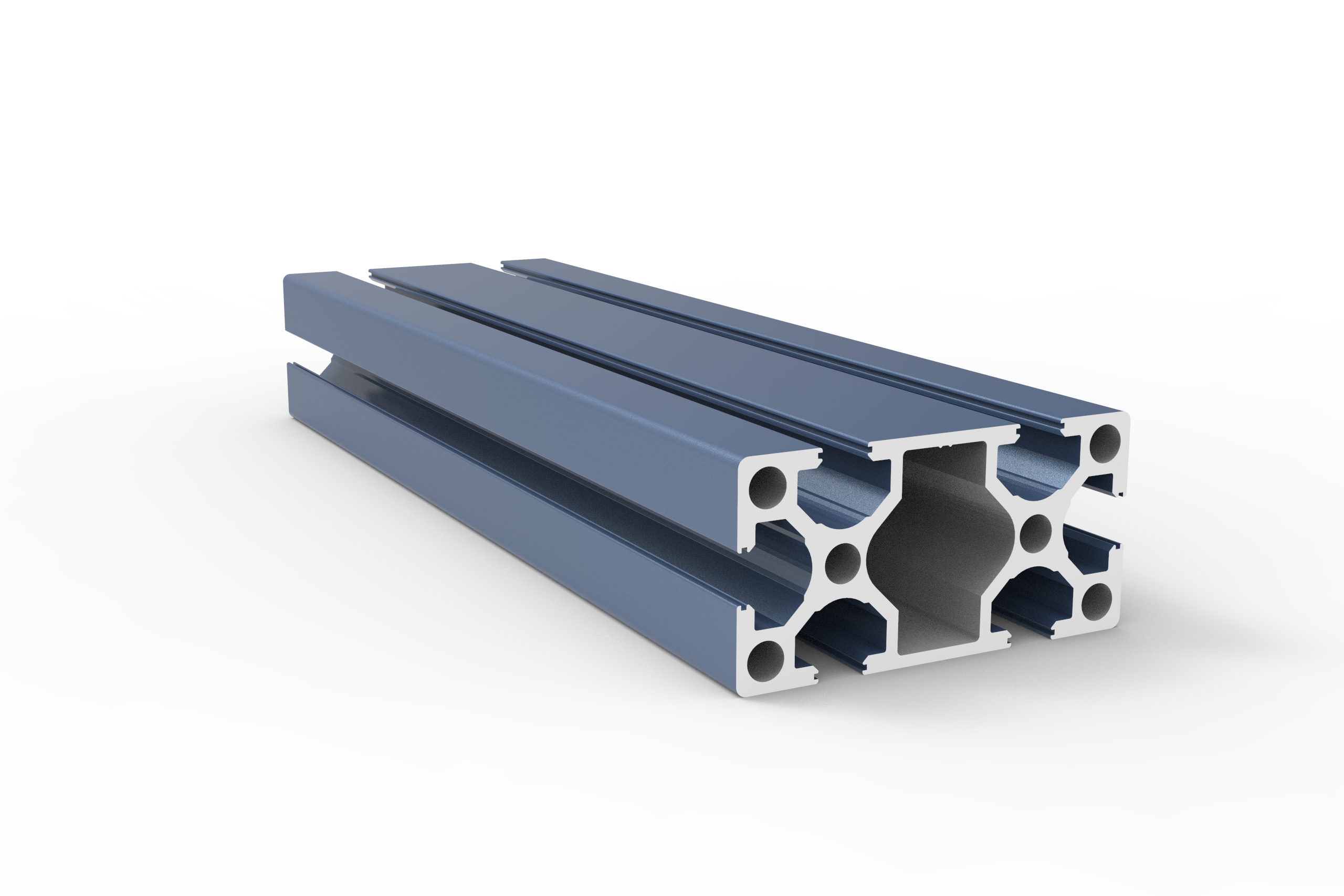
What T-slot industrial profile size is best for a heavy duty machine frame?
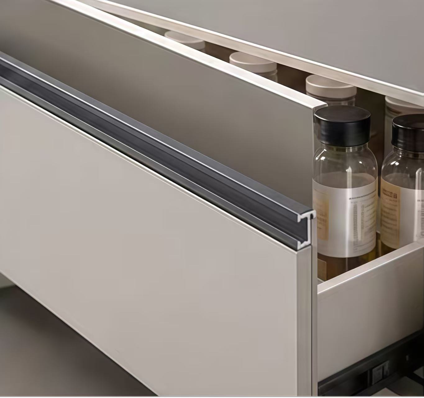
How do I choose the right stainless steel decorative profile for high humidity areas?
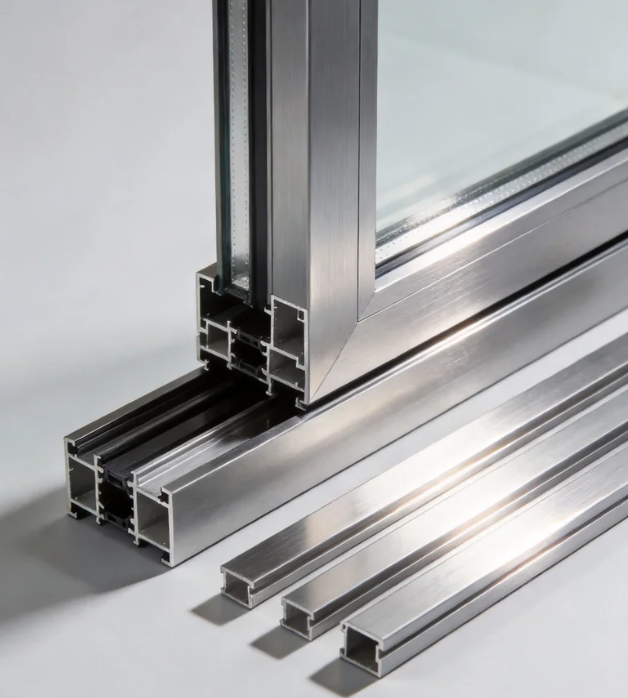
How do I choose the right aluminum architecture profile for coastal buildings?
How do I choose the right stainless steel decorative profile for high humidity areas?
What wind load specs should I check for aluminum casement windows in coastal high-rises?
How do I know which aluminum industrial profile alloy is best for heavy machinery frames?
How do I choose the right alloy grade for aluminum architecture profiles?
How do I select the right heavy-duty hardware for exterior commercial floding doors?
How do I select the right glass thickness for bulk awing window orders?
What frame thickness is recommended for commercial aluminum casement doors?
What frame thickness is best for high-rise commercial sliding windows?
How to choose weather resistant aluminum floding door specs for commercial use?
How do I choose the best water tightness rating for commercial awing windows?
How do I choose the right frame material for commercial casement doors?
How do I choose the right wind load rating for sliding windows in coastal areas?
What is the best material for outdoor decorative profiles to prevent rust and fading?
How do I choose the right track thickness for high-traffic commercial sliding doors?
How do I choose between PVC and basswood shutters for high-humidity areas?
How do I choose between double and triple glazing for casement windows in cold climates?
How do I choose the right industrial profile thickness for heavy-duty cnc machine frames?
How do I choose the right alloy for outdoor architecture profiles to prevent corrosion?
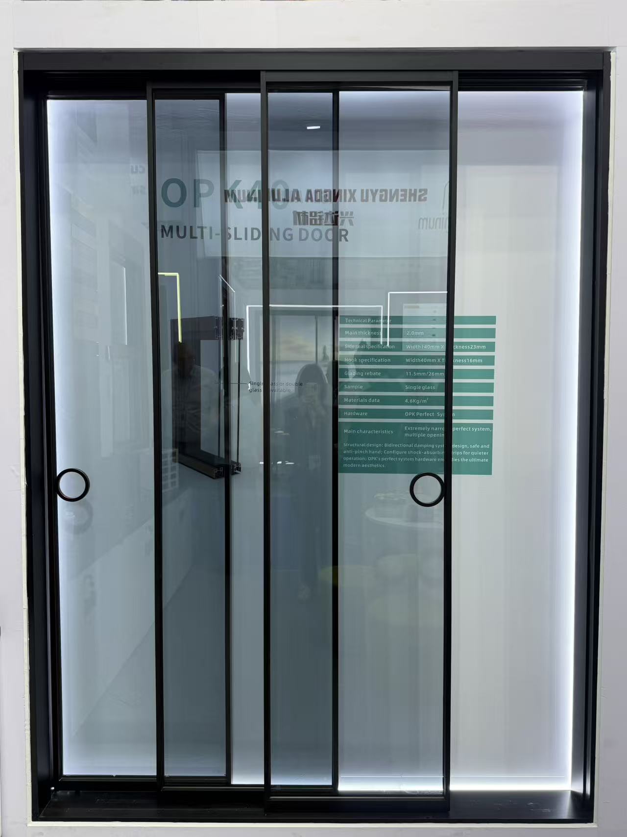
Can you design a slim frame profile for modern minimalist look?
How do I choose the right wind-resistant floding door for a coastal commercial building?
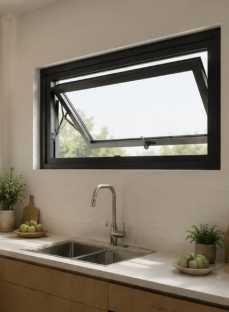
What key specs ensure a casement window can withstand heavy rain and high winds?
How do I choose the right aluminum alloy grade for heavy-duty industrial profiles?
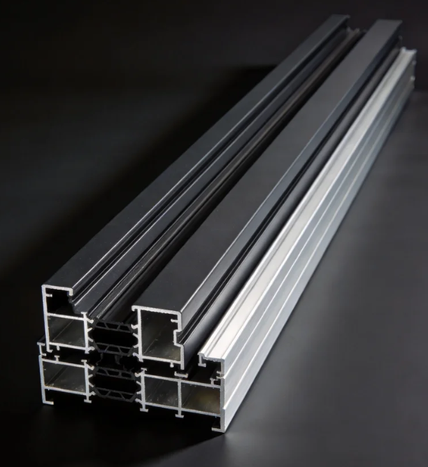
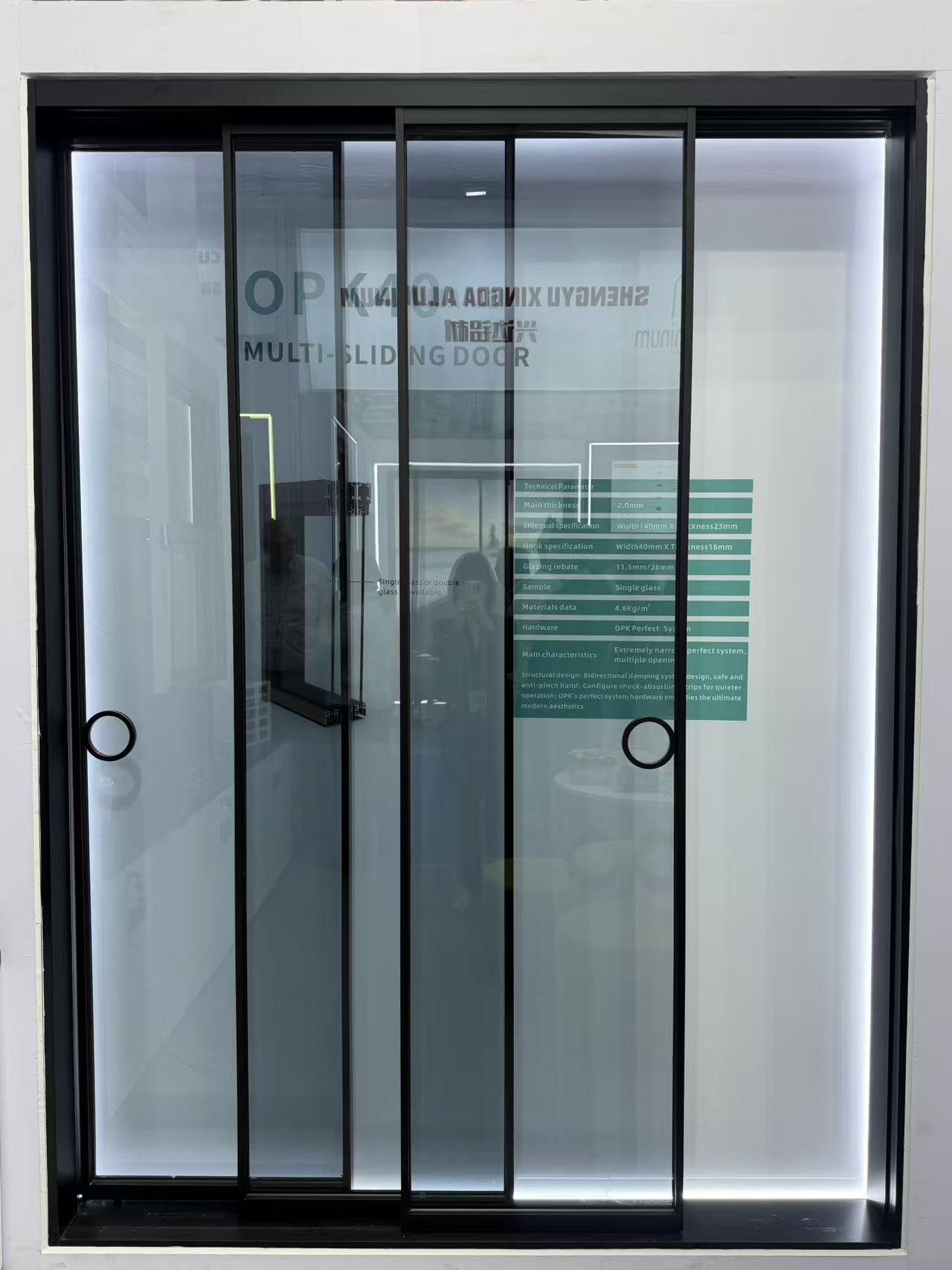
Which alloy grade of architecture profile is best for coastal areas to resist rust?
How do you pack windows to prevent glass breakage in transit?
Are slim-frame thermal break systems replacing traditional ones?
Does the price include the matching frame and installation kit?
How do you protect our proprietary design drawings from leaks?
How do I choose the right decorative profile for high-traffic hotel lobbies?
Is your factory the actual manufacturer or a trading partner?
Is it possible to 3D print a prototype before cutting steel?
Do you outsource any part of the painting process to others?
How do you handle replacement parts for damaged track rollers?
Do you accept escrow payments through third-party platforms?
Do you have ISO 9001 certification for your production line?
Are there extra fees if we pay via bank telegraphic transfer?
What is the price difference between powder coat and anodized?
What is the warranty period for the lock and hinge hardware?
What is your policy for dimensional deviations in the batch?
What happens if the shipment is delayed due to factory error?
Do you offer online technical support if color fading occurs?
Is it possible to engrave our brand logo on the tension screw?
Do you offer credit terms for long-term purchasing partners?
Can you palletize the shipments for easy forklift unloading?
What are the latest eco-friendly finish trends for decorative profiles in modern interior design?
What are the tooling cost and design limitations for customizing heavy-duty industrial profiles?
Has your architecture profile manufacturing facility passed ISO 9001 certification?
Can we use Alibaba Trade Assurance for our initial sliding door order to mitigate risk?
Do you provide free corner samples of the casement window frame for color verification?
Is it possible to custom-match a specific RAL color for a decorative profile order?
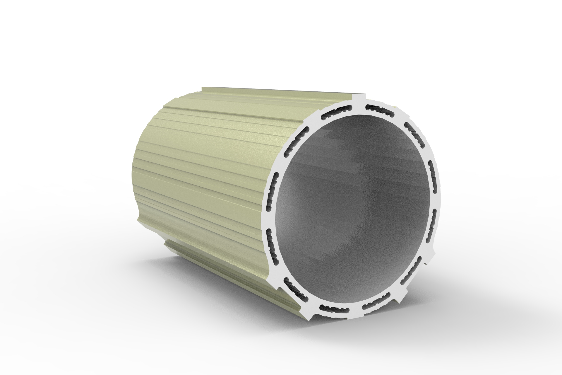
Can I request a 3D-printed sample before ordering a custom industrial profile mold?
Can you extrude an architecture profile based on our proprietary CAD drawings?
What thermal performance certifications does a sliding door need for the UK market?
How are heavy floding door panels crated to ensure safe unloading at the job site?
Can we arrange our own freight forwarder to pick up the casement door shipment FOB?
What is the estimated ocean freight transit time for a shutter shipment from China to Europe?
How can we source replacement seals for your awing window models in the future?
How are sliding windows typically packaged to prevent glass breakage during ocean transit?
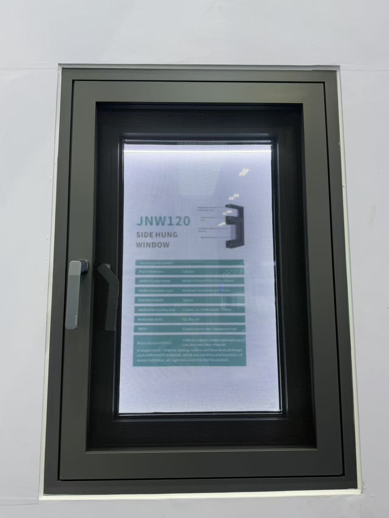
What is the average lead time for a 40ft container of standard aluminum casement windows?
Are there any extra tooling fees if my decorative profile order doesn’t meet the MOQ?
Can I get 3D printed prototypes of custom architecture profiles before committing to mold tooling?
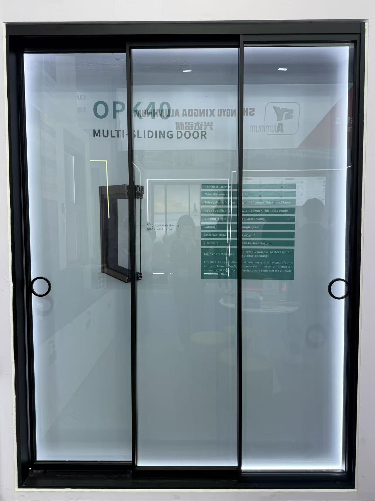
How is smart glass technology being integrated into modern residential sliding door units?
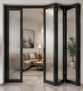
What options do you have for customizing the threshold height of an aluminum floding door?
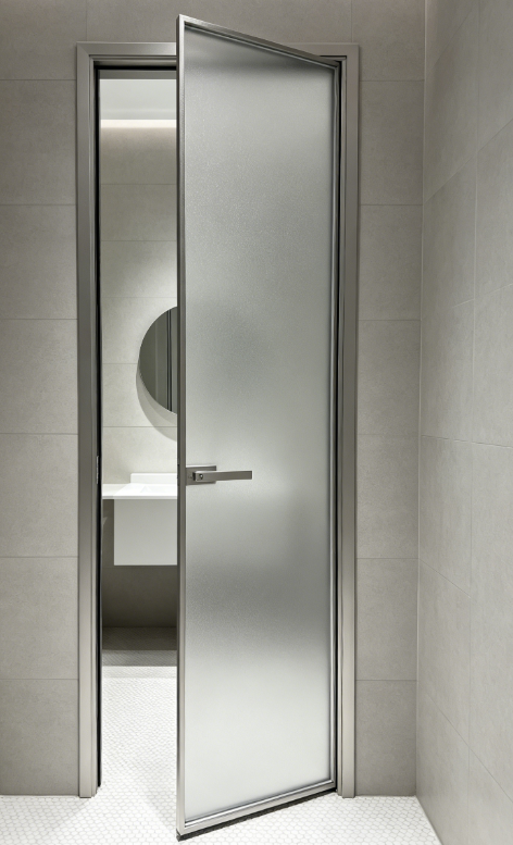
What thermal break technology should I look for in a heavy-duty aluminum casement door?
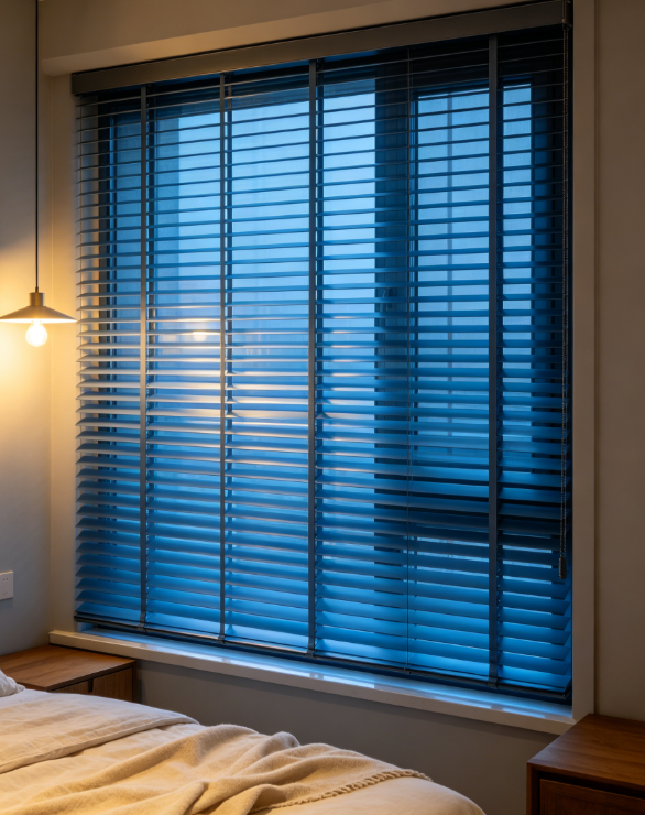
What quality control processes do you perform on shutter hardware before final assembly?
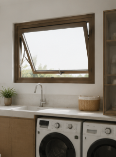
Do you offer DDP shipping terms for awing window orders delivered to our warehouse?
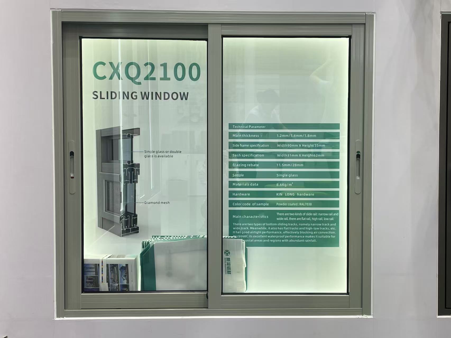
Is it possible to order a fully functional sliding window sample for mock-up testing?
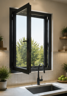
Do you provide replacement hardware if the casement window hinges fail within 5 years?
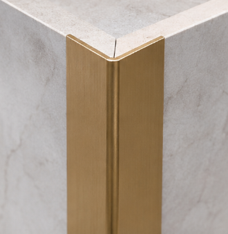
How do you handle claims for decorative profile items damaged during transit?
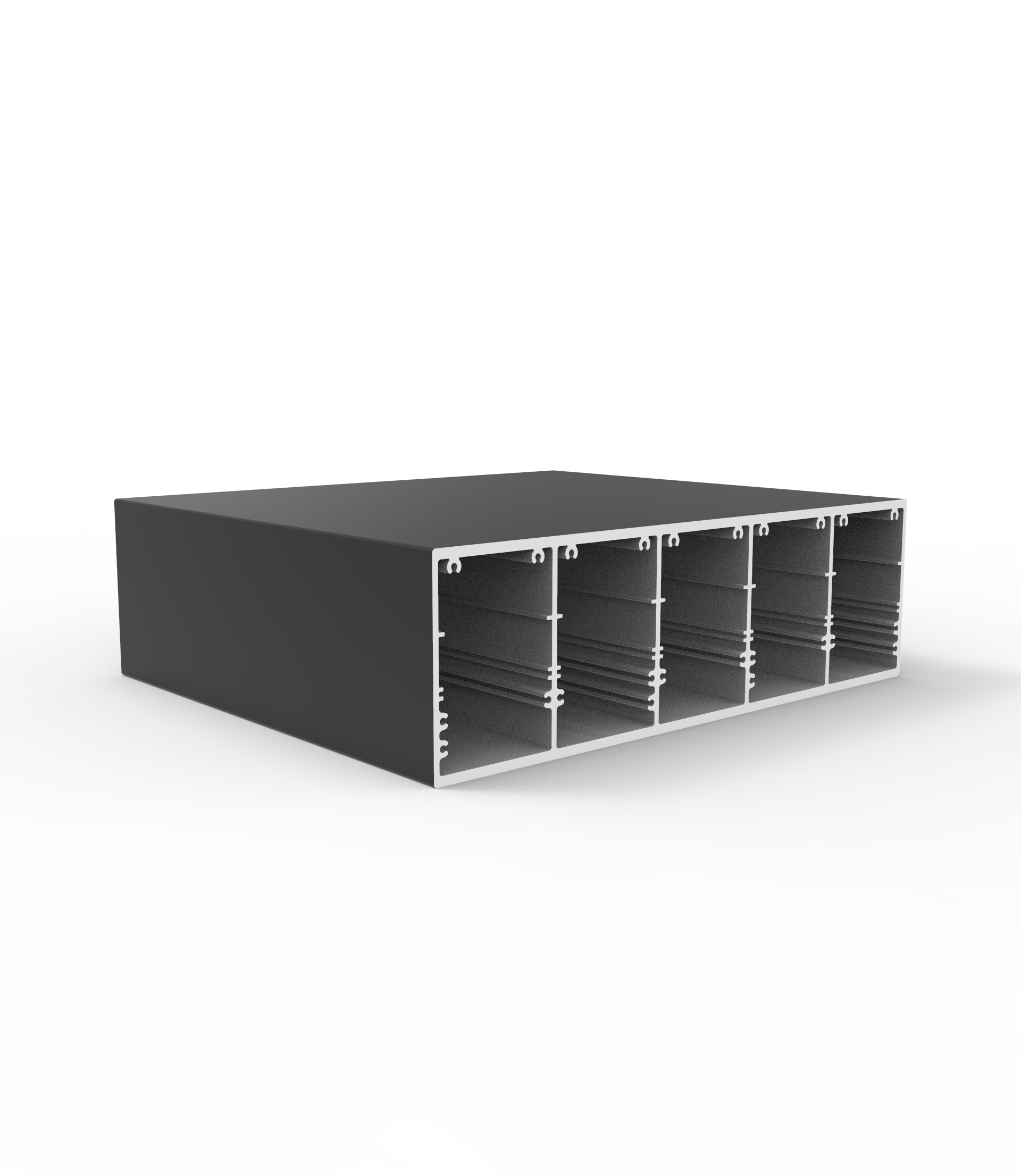
What is the standard MOQ for custom-extruded aluminum industrial profile orders?
How does the order volume affect the per-ton price of custom architecture profile designs?
What is the warranty period for the rollers and tracks on your heavy-duty sliding doors?
How can we secure our deposit when purchasing high-value custom floding doors from a new supplier?
Can your factory match custom anodized colors for decorative profiles based on physical samples?
Is there a lighter alternative to aluminum industrial profile structures for robotics?
What payment security measures do you have for custom architecture profile tooling fees?
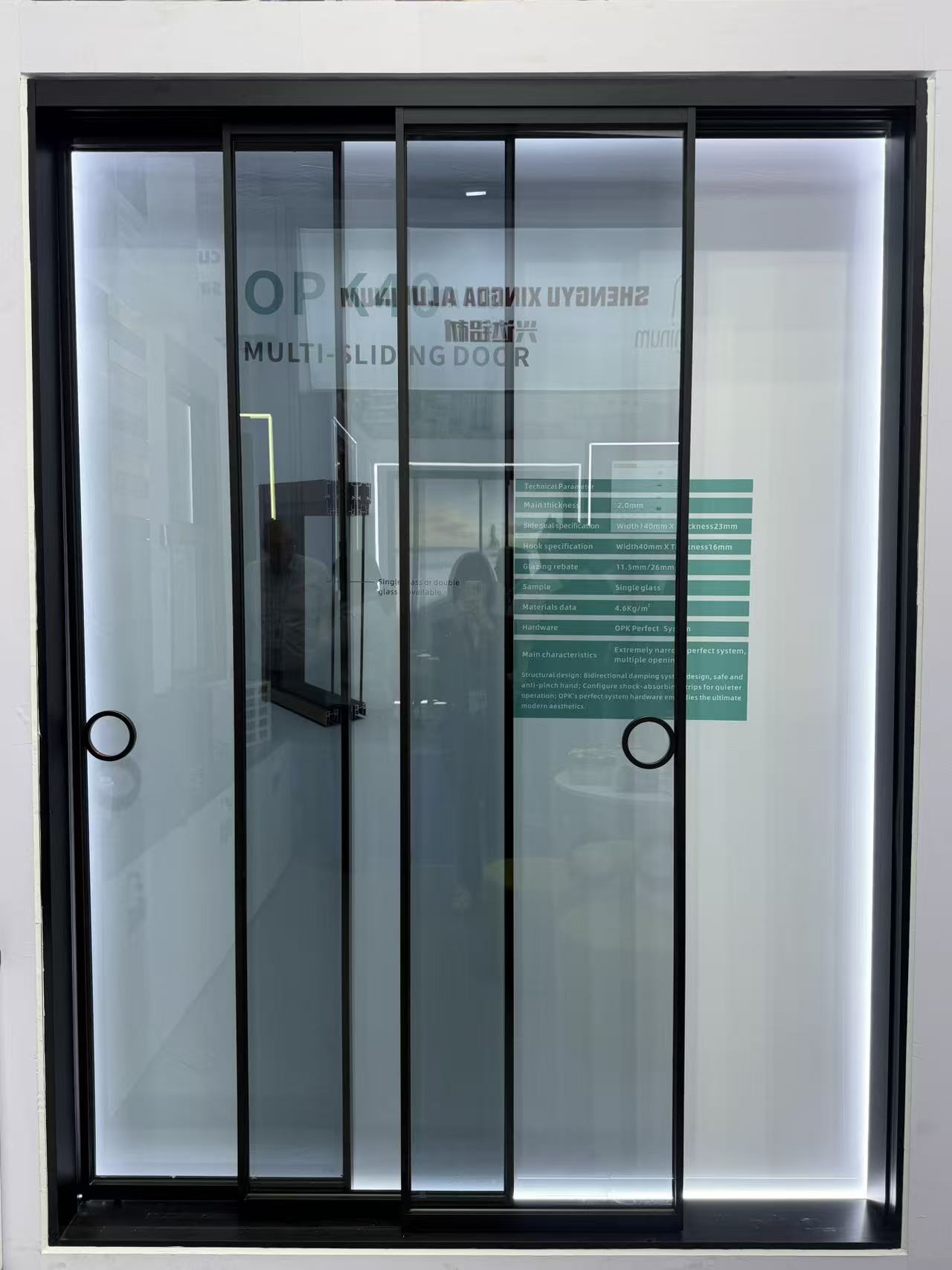
Can I order a sliding door with custom grid patterns between the glass panes?
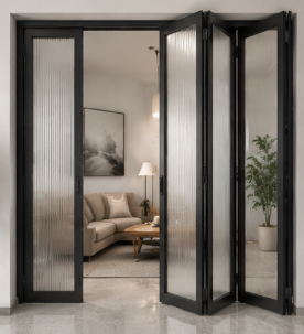
How do you protect buyers against financial loss if the floding door shipment is delayed?
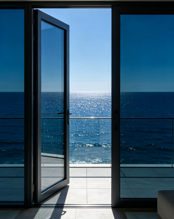
Are slim-frame aluminum casement door designs becoming more popular in modern offices?
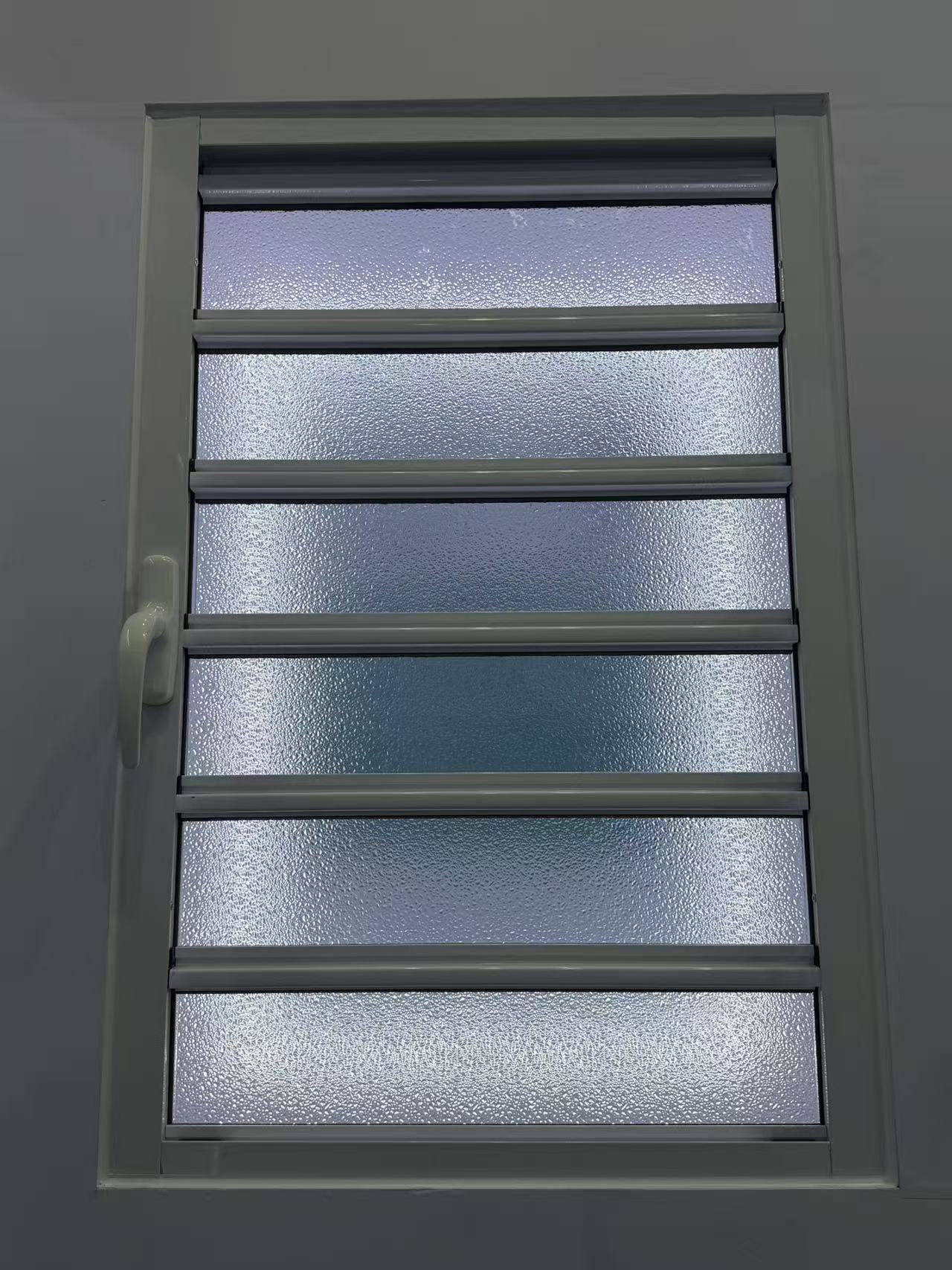
What is your policy for replacing shutter components that arrive with color mismatch?
What kind of remote technical support do you offer for sliding window installation?
What is the maximum safe size for a top-hung awing window in commercial projects?
What environmental management standards does your decorative profile plant follow?
What is the standard lead time for producing a 40ft container of casement window orders?
What is the warranty period for the anodized finish on your industrial profile?
What are the latest eco-friendly trends in architecture profile manufacturing?
What is the average wholesale price per square meter for double-glazed sliding door systems?
How do I calculate the structural load requirement for a 5-panel exterior floding door?
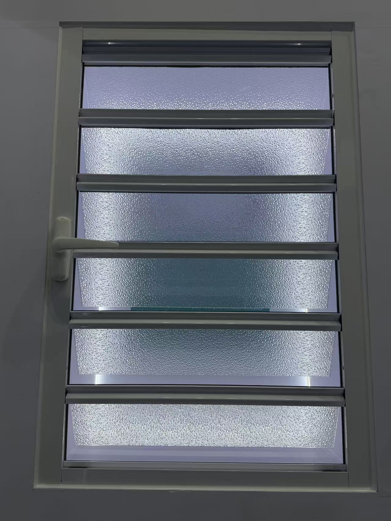
Do your exterior shutter systems comply with Florida building codes for hurricane protection?
Do you offer Letter of Credit (L/C) payment options for casement door bulk orders?
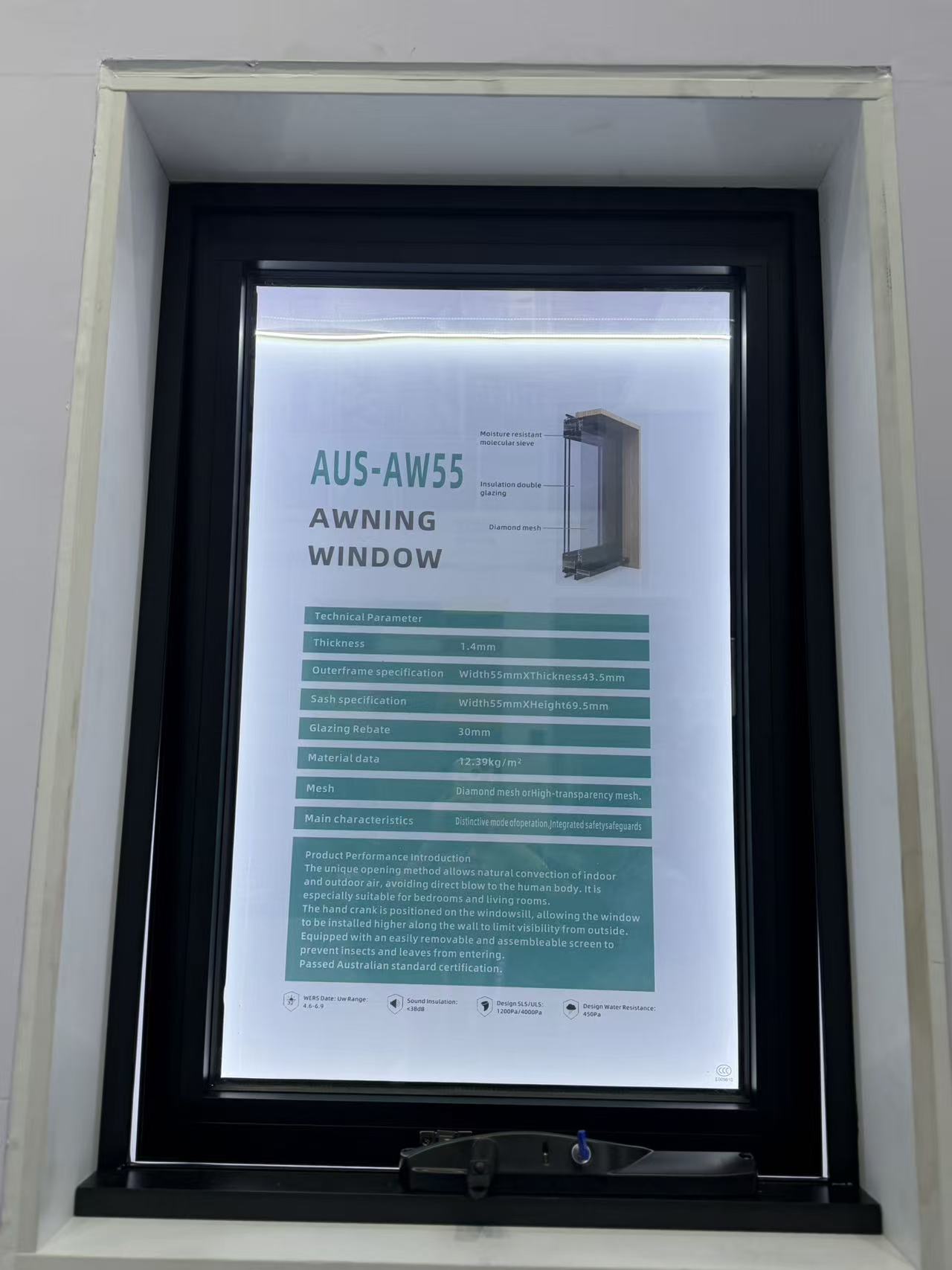
Which water tightness certifications are required for importing an awing window to Europe?
Do you allow virtual factory tours to inspect the sliding window assembly line?
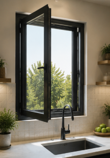
What is the typical MOQ for ordering standard-sized aluminum casement window units?
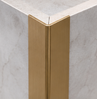
How long does it take to receive a physical sample of a gold-anodized decorative profile?
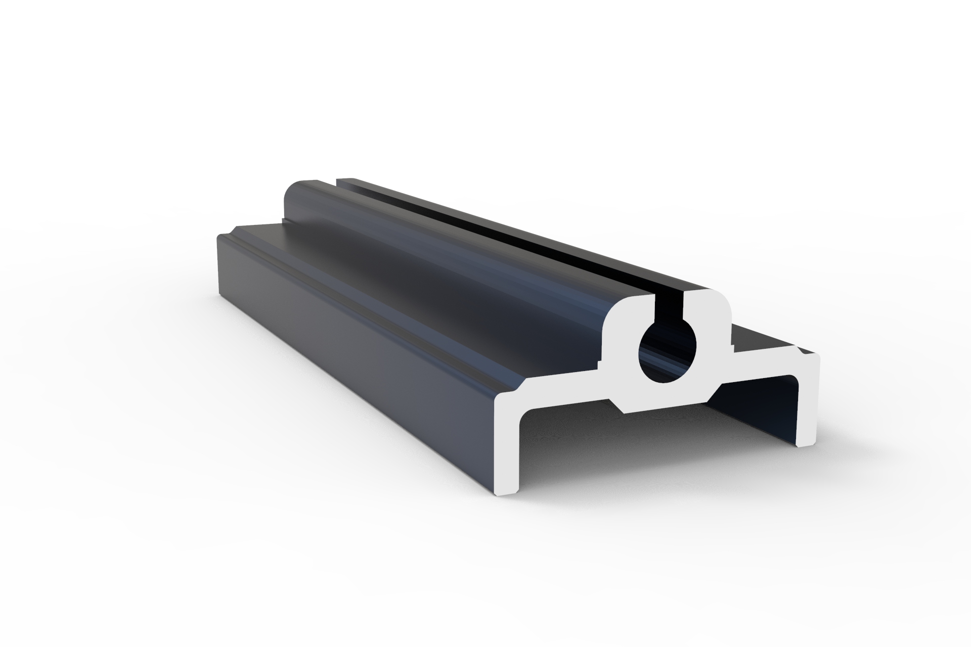
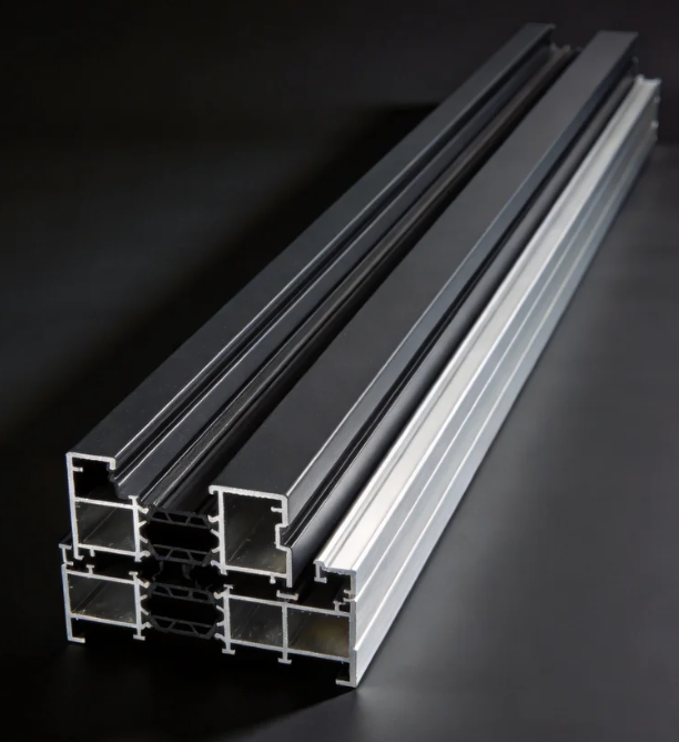
How do I choose the right alloy grade for architecture profiles in high-rise coastal buildings?
How do I choose the right track and roller specs for heavy-duty commercial sliding doors?
The core advantages of using aluminium profiles for the canopy
International demand: Dual drive by new energy and infrastructure
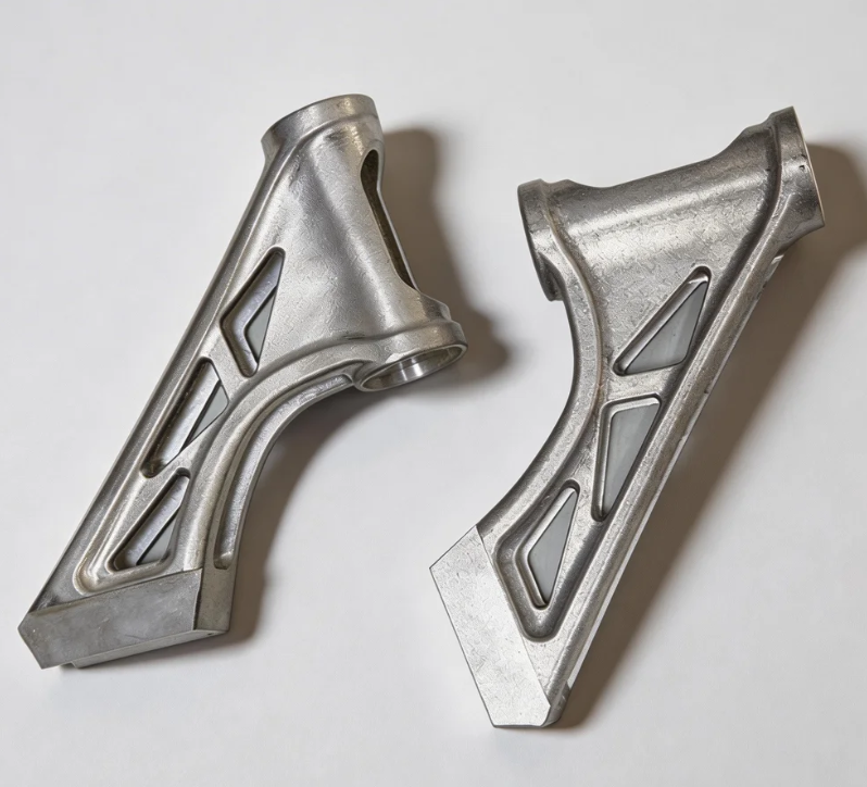

The advantages of using aluminium profiles to manufacture robot arms
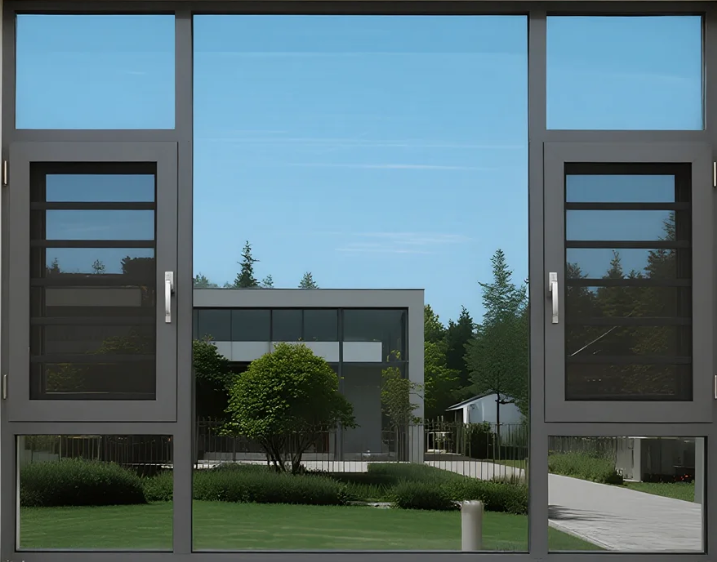
The advantages of using aluminum profiles for door and window frames
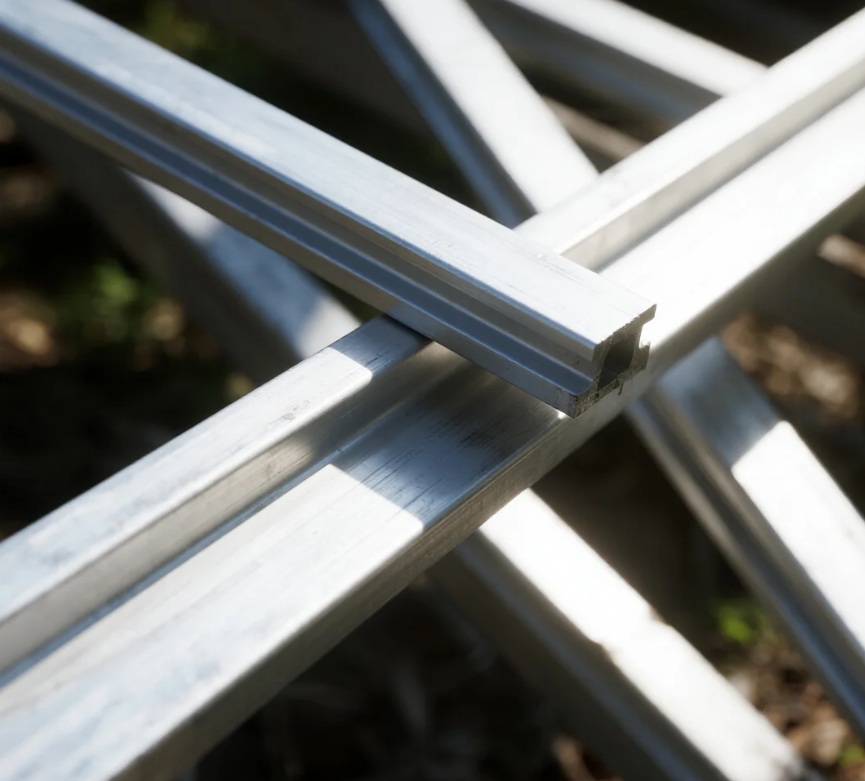
The impact of the conflict between the United States and Iran on the price of aluminum
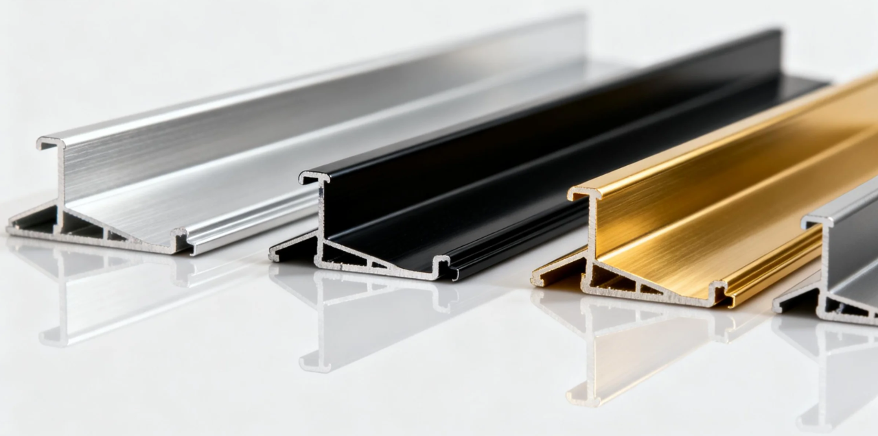
The advantages of using aluminium alloy for the main structure of high-speed train carriages
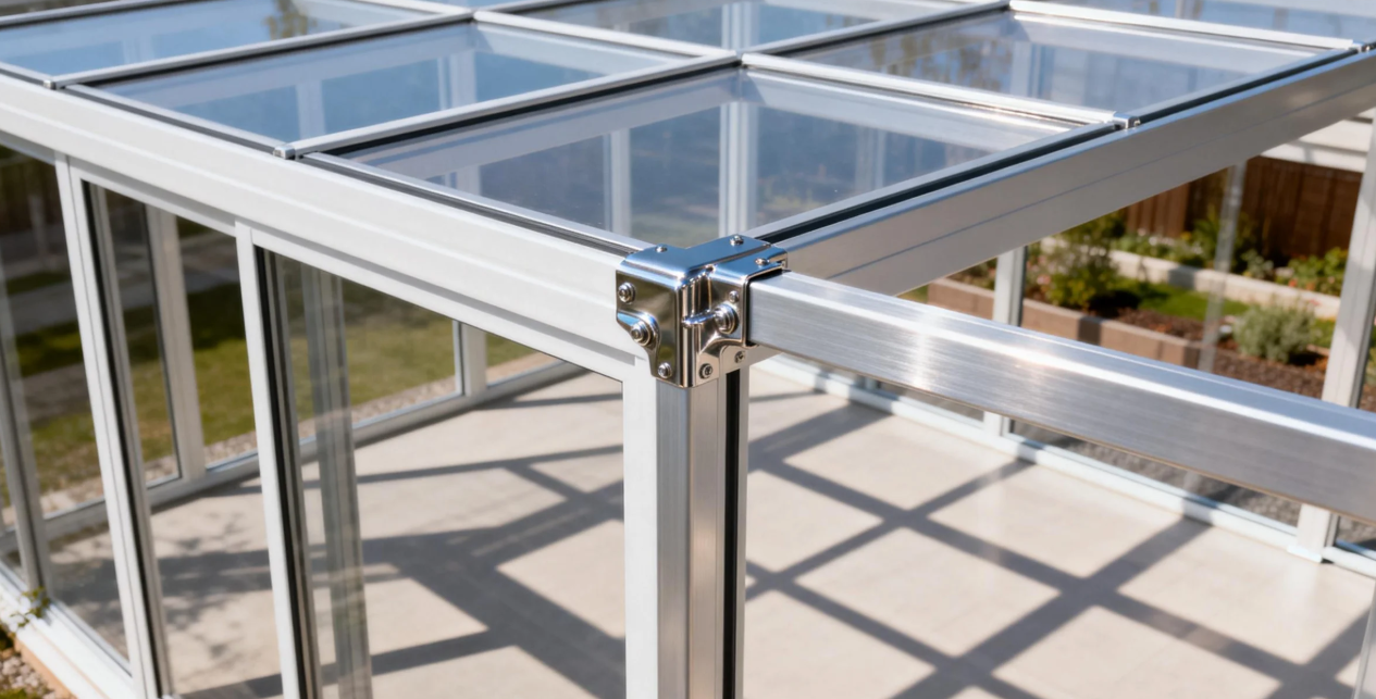
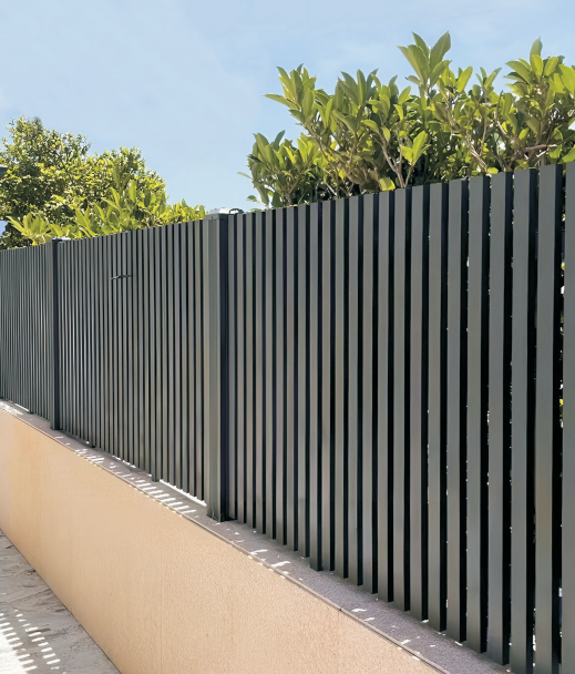
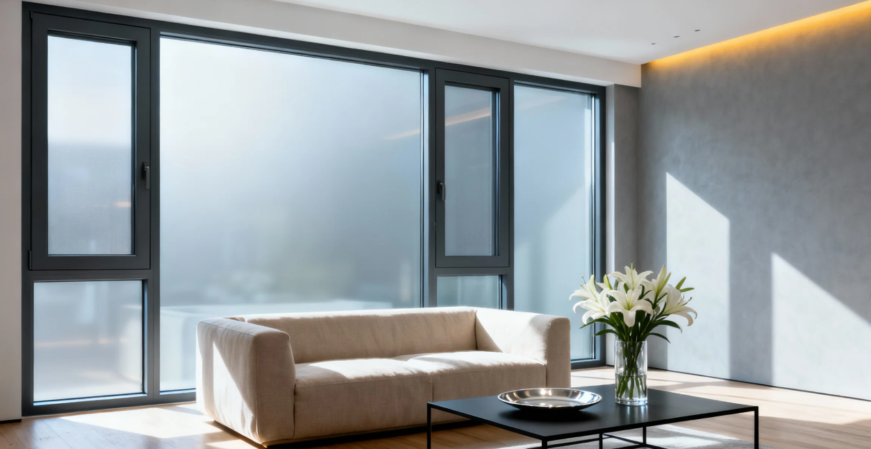


Methods for distinguishing Indoor and Outdoor Aluminium Doors
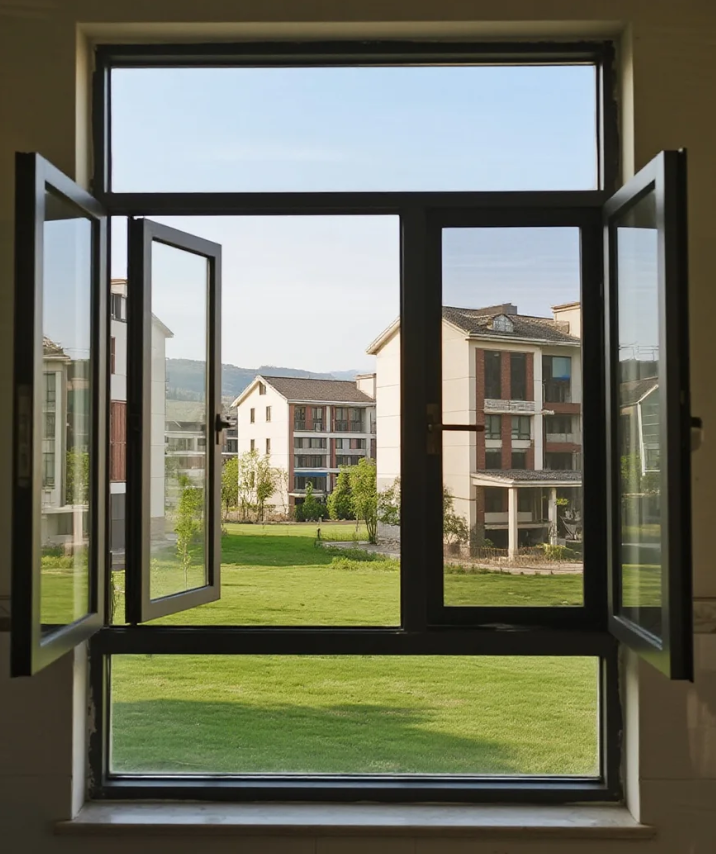
Maintenance methods and tips for aluminium doors and windows
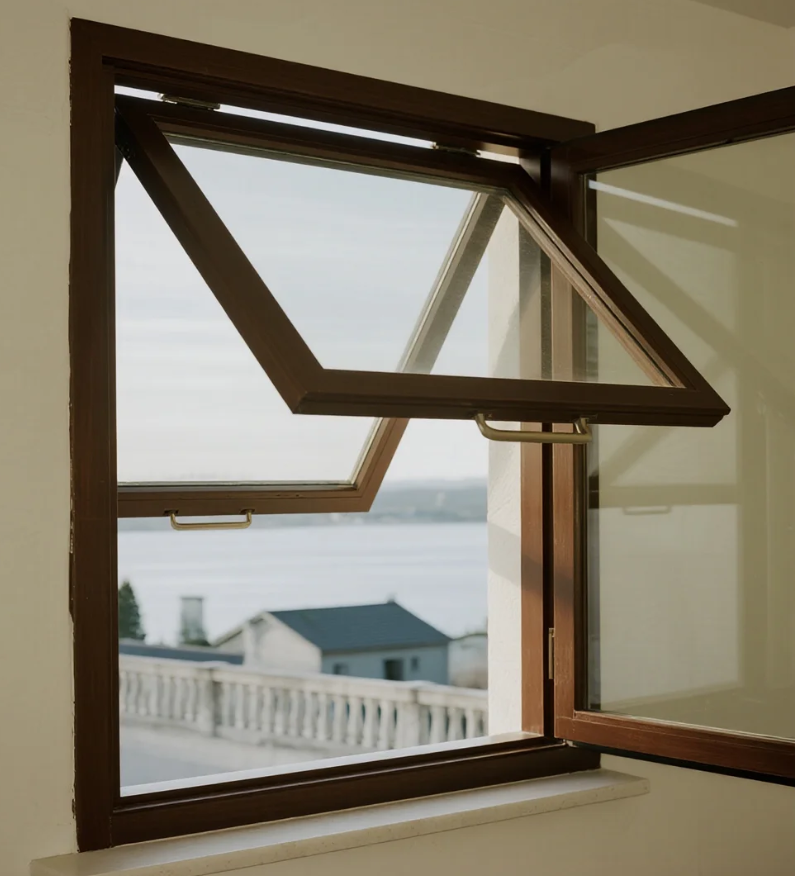
Characteristic of outward-opening and hung aluminium windows


Xinhe Aluminium Research: 7.14-7.18 Analysis of Aluminium Prices
Seven Benefits Of Using Aluminium Profiles In Curtain Wall Systems
The Application of Aluminium Profiles in New Energy Vehicles

The Composition and Application of Series 6 Aluminium Alloys
Top 5 Benefits of Using LED Aluminium Profiles in Modern Lighting
A Complete Guide to Aluminium Frame Profiles for Modern Structures
Exploring the Strength and Versatility of Aluminium Extrusion Profiles
How to Choose the Right Aluminium Profile Supplier for Your Project

COMPANY