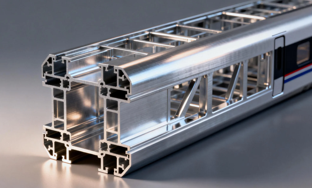
Modern railway engineering faces a continuous battle against dead weight. High-speed trains operating at elevated velocities require immense kinetic energy just to overcome their own static mass. Reducing the structural mass of the rolling stock directly translates to lower energy consumption and reduced track wear. Properly engineered extruded aluminium profiles serve as the foundation for this critical mechanical shift.
Every kilogram saved in the body shell allows for faster acceleration and shorter braking distances. Engineers historically relied on heavy steel frameworks to handle the severe dynamic loads of rail transport. Steel offers excellent absolute strength, but the severe penalty lies in its raw material density.
Aluminium components cut structural weight to roughly one-third that of traditional steel assemblies. This massive reduction in dead weight fundamentally alters the operational economics of a railway network. Lighter trains require less electrical current from the catenary wires during peak acceleration phases.
Less weight also means less severe track degradation over time. Unsprung mass and overall axle loads dictate the maintenance schedule for the entire rail infrastructure. By integrating lightweight structural framing, transit authorities extend the lifespan of their expensive track networks.
Rail vehicles do not operate in a smooth, static environment. A train traveling at 250 to 350 kilometers per hour experiences continuous, high-frequency vibrations transmitted directly from the steel wheels interacting with the steel rails. These vibrations propagate upward through the chassis and into the main body shell.
Metals subjected to continuous vibration risk catastrophic failure through mechanical fatigue. Micro-cracks can initiate at stress concentration points and propagate through the crystal lattice of the metal. If the structural material cannot absorb or distribute these dynamic shock loads, the framework will eventually fracture.
The hollow internal geometries achievable with extrusion provide an elegant solution to this vibration problem. Engineers design specific cross-sections that intentionally dissipate vibrational energy before it reaches the passenger cabin. The flexibility of the metal, combined with precise wall thicknesses, acts as a macroscopic dampening mechanism.
Solid metal beams transfer vibration almost perfectly from one end to the other. Complex hollow shapes interrupt these vibrational pathways through their internal webbing. This structural dampening is critical for maintaining passenger comfort during long-haul journeys at maximum operating speeds.
The true engineering advantage of an extrusion does not lie in the metal itself. The advantage lies in the ability to place material exactly where it is needed to resist physical forces. Bending stiffness is determined by the area moment of inertia, which dictates how material is distributed away from the neutral axis.
A simple hollow square tube offers good bending resistance but suffers from structural instability under diagonal shear forces. If you push on the corner of a hollow square, it will easily deform into a parallelogram. This deformation is entirely unacceptable in a rigid high-speed rail chassis.

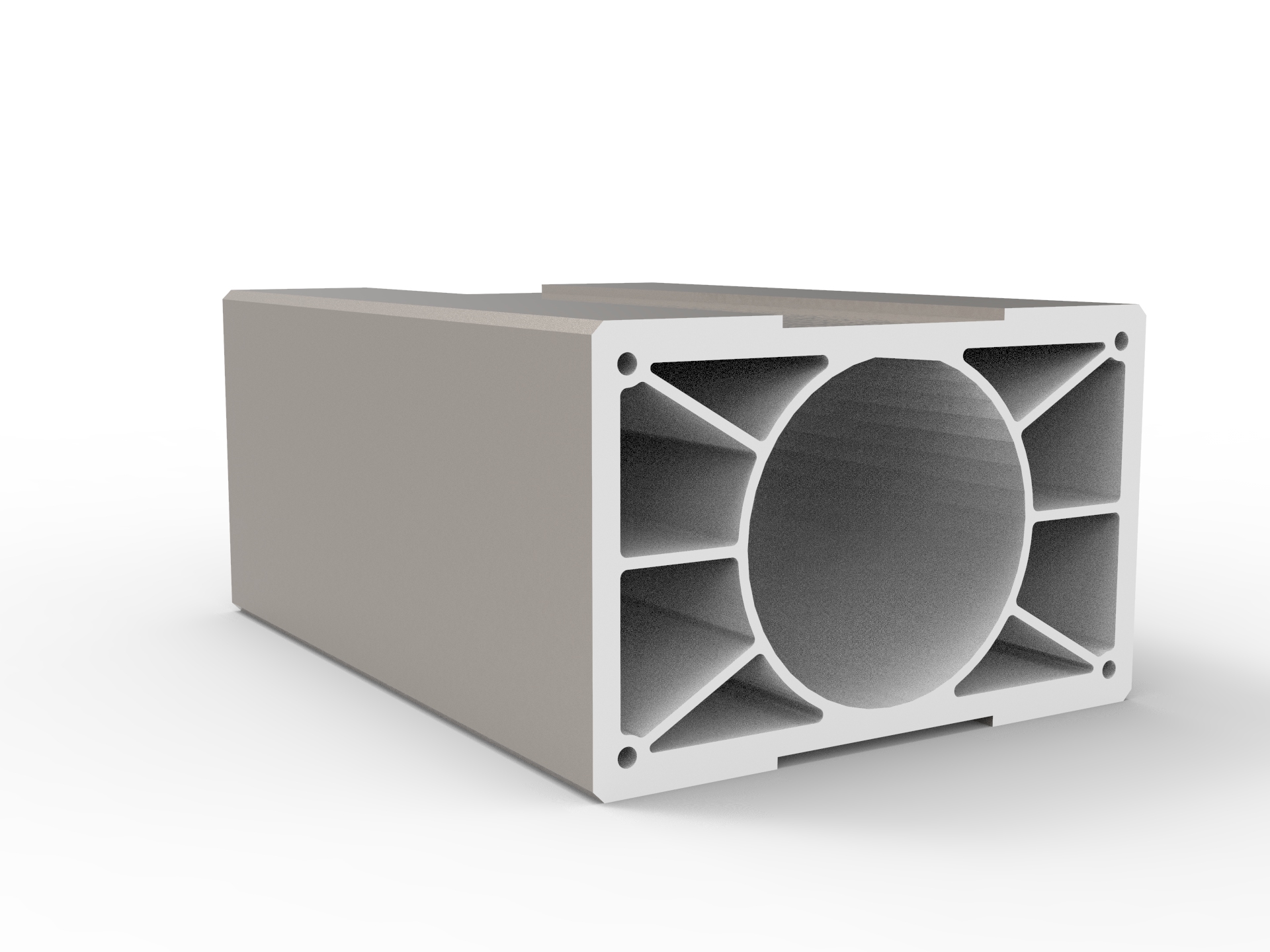
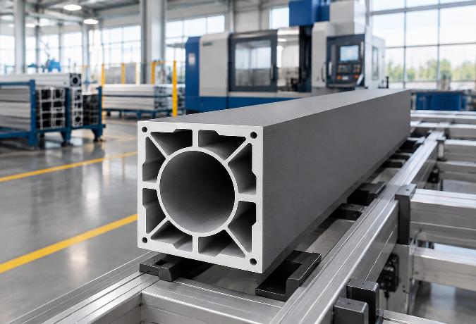
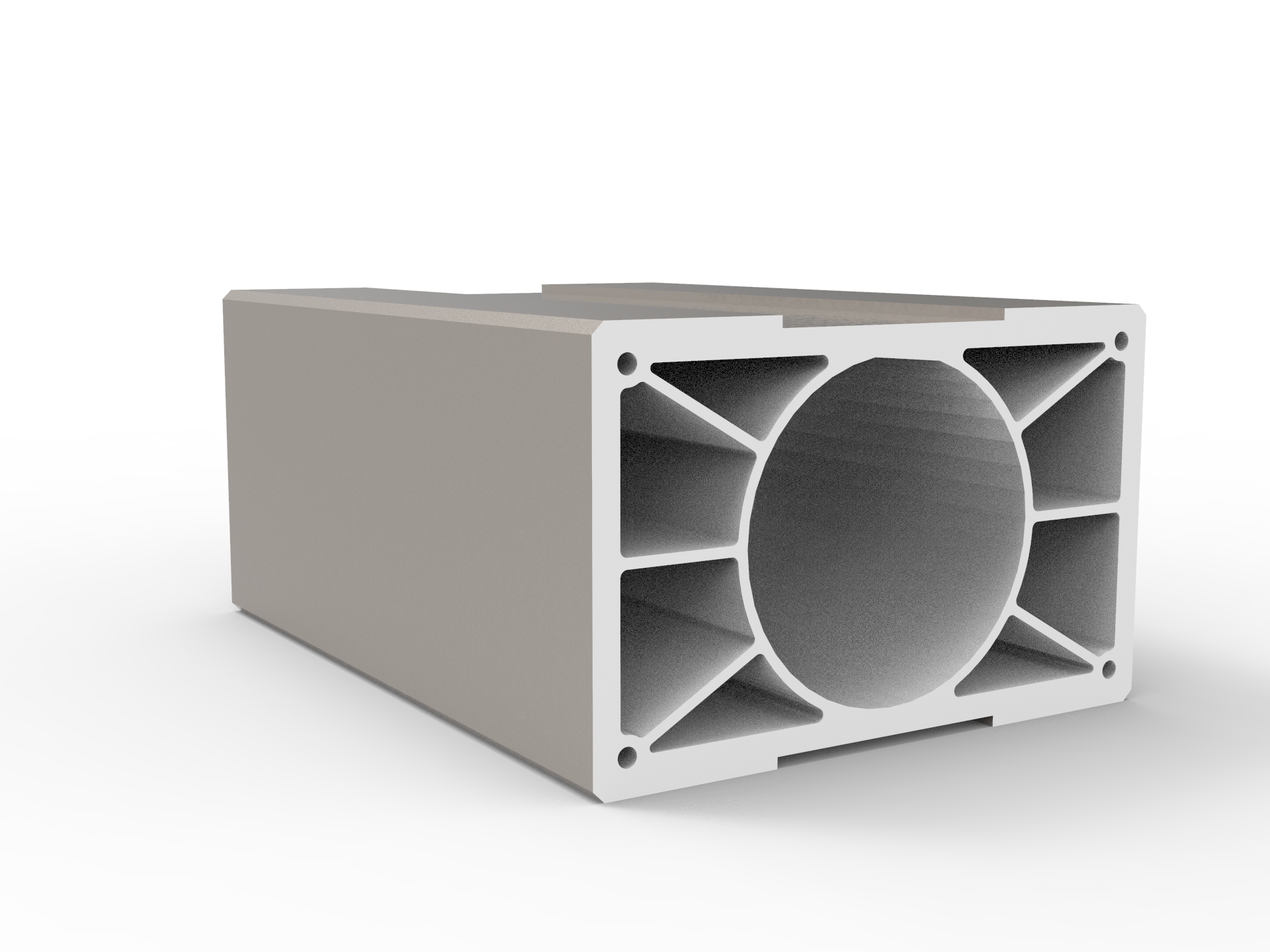
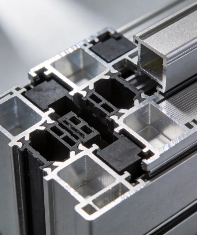
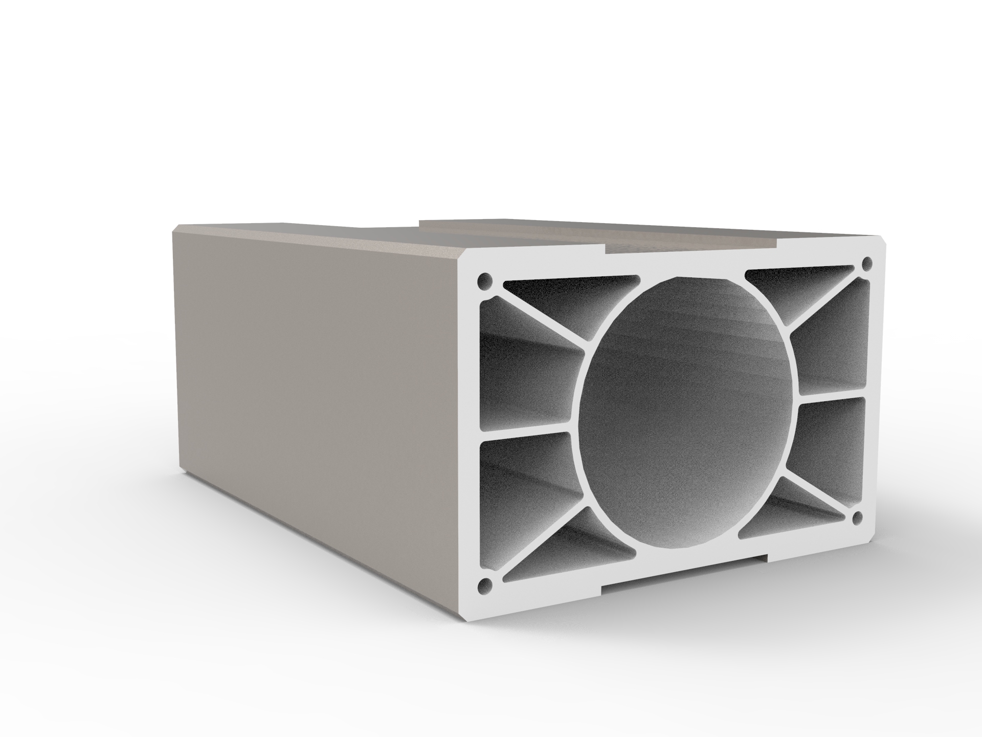
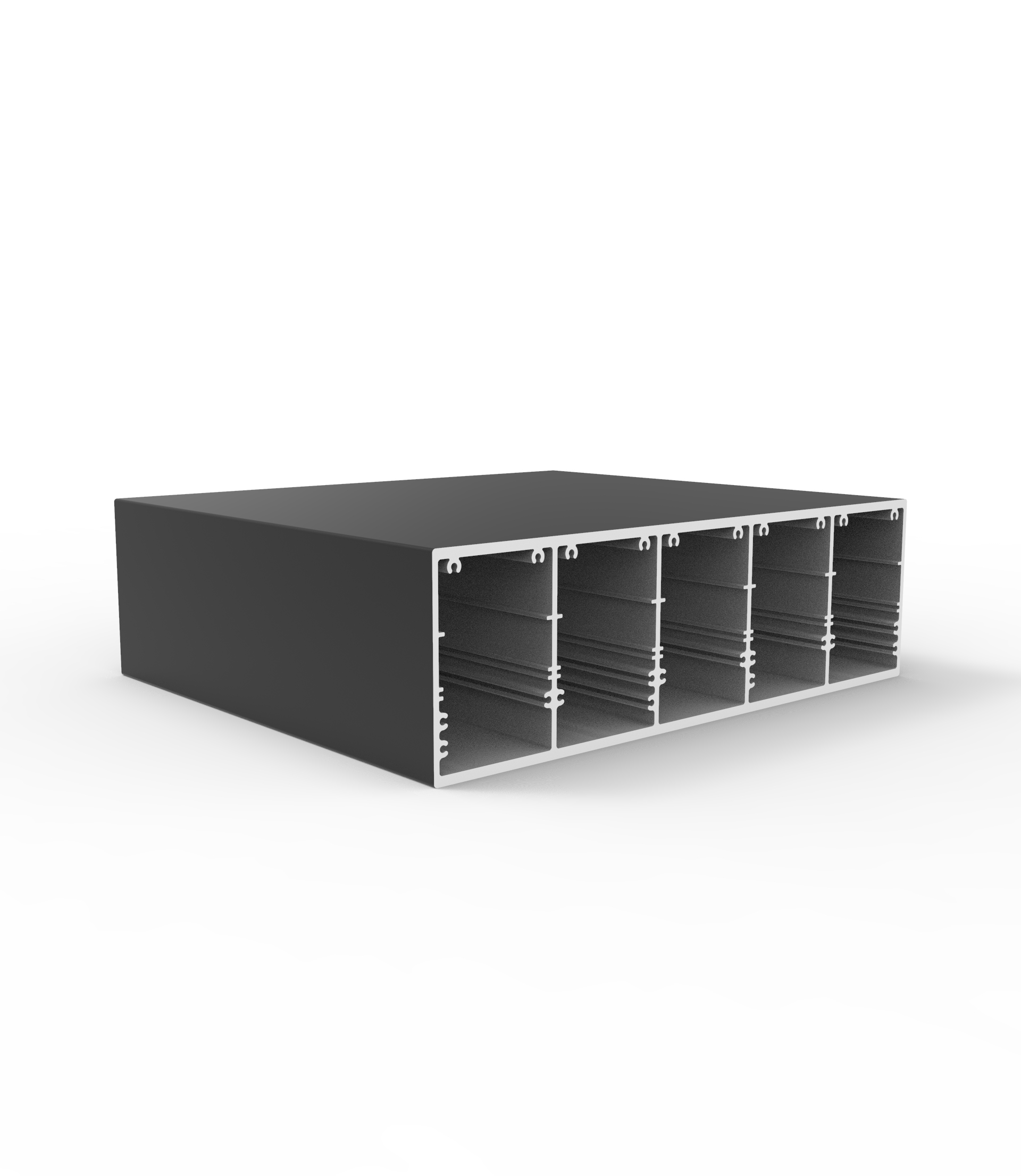
To prevent this deformation, dies are machined to create a hollow triangular multi-rib internal geometry. Triangles are structurally stable geometric shapes that cannot be deformed without altering the physical length of their sides. By webbing the interior of a hollow profile with interconnected triangular ribs, the profile gains immense shear stiffness.
This internal truss system locks the exterior walls in place. When a dynamic shock load hits the exterior surface, the force is immediately distributed across multiple internal diagonal bulkheads. Localized buckling is prevented because the triangular ribs brace the thin outer walls against inward deflection.
Not all aluminium is suitable for the severe mechanical stresses of railway applications. Industrial rail engineering primarily relies on the 6xxx series alloys, specifically 6063, 6060, and 6061. These alloys use magnesium and silicon as their primary alloying elements to achieve a specific balance of extrudability and strength.
The 6061 alloy contains a slightly higher concentration of these elements, plus copper, making it structurally robust for heavy load-bearing chassis components. The 6063 and 6060 alloys offer superior extrudability. This allows them to flow smoothly through complex dies to form very thin, precise internal multi-cavity ribbing without tearing.
The raw extrusion process is only half of the metallurgical equation. The profiles must undergo a specific thermal treatment process to achieve their T5 or T6 temper designations. The T6 temper involves solution heat-treating the metal at a high temperature, rapidly quenching it, and then artificially aging it in an oven.
During this artificial aging process, microscopic precipitates of magnesium silicide form within the aluminium crystal lattice. These microscopic particles act like physical roadblocks, pinning dislocations in place and preventing the metal planes from sliding past one another. This precipitation hardening is what gives the T6 alloys their exceptional yield strength.
The application of these specialized metals extends far beyond the main exterior body shell. The interior of the passenger compartment relies entirely on lightweight metal frameworks to support walls, floors, and seating systems. Every internal component must adhere to the same strict weight-reduction protocols as the primary chassis.
Rolling stock underframes and structural floor profiles must support the dynamic weight of hundreds of passengers. These floor assemblies utilize wide, flat profiles with dense internal stiffening ribs. They provide a rigid, flat surface for mounting flooring materials while maintaining a remarkably low profile height.
Partition walls between rail cars or structural dividers within the cabin utilize thinner, interlocking profiles. These components need to be rigid enough to hold heavy glass doors and electronic displays without swaying during transit. The interlocking designs allow for rapid assembly inside the rail car without relying on heavy welded steel brackets.

The ability to create custom cross-sections means engineers can integrate functional features directly into the structural support. Channels for wiring harnesses, mounting grooves for interior paneling, and sliding tracks for doors can be extruded directly into the wall profile. This integration eliminates the need for secondary machining and fastening.
Passenger seating represents a significant portion of the total interior mass of a train car. A standard eight-car high-speed train carries approximately 480 to 600 seats, each requiring a heavy, crash-rated structural frame. Replacing standard steel seat bases with precision-engineered metals creates an immediate and measurable reduction in overall cabin weight.

These specialized high-speed rail passenger seating frames must survive severe physical testing. The seat base cannot simply hold static weight; it must absorb extreme forward momentum during an emergency deceleration event. The hollow internal matrix is engineered to remain rigid under normal loads but crumple predictably during a catastrophic impact.

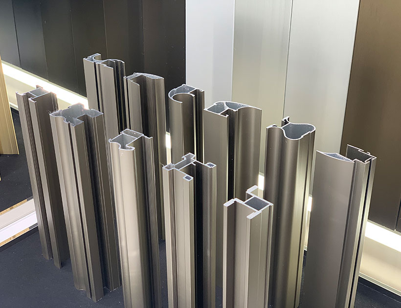
The backrest sections utilize vertical-to-curved support plates integrated with multi-cell triangular structures. This geometry provides absolute rigidity against the leverage exerted when a passenger leans heavily against the top of the seat. The surface is given a clean, uniform satin-finished metallic sheen to match the modern aesthetic of the cabin.

Lower horizontal seat bases feature tapered cross-sections designed to distribute loads evenly into the structural floor tracks. The complex interlocking bottom connector channels are extruded directly into the shape. This allows the seating units to slide securely into the rail car floor without complex bolting hardware.
Trains operate in highly corrosive outdoor environments. They face constant exposure to acid rain, industrial pollutants, high humidity, and occasionally coastal salt spray. Unprotected metal surfaces will quickly pit, degrade, and lose their structural integrity under these harsh atmospheric conditions.
To combat environmental degradation, the surface of the metal is treated using advanced electrochemical or chemical bonding processes. A basic mill finish is suitable for completely enclosed internal structures. Exterior or exposed components require significant chemical protection to guarantee a long operational lifespan.
Anodizing is the most critical surface treatment for load-bearing rail components. This electrochemical process artificially thickens the natural oxide layer on the surface of the metal. The resulting anodic layer is actually harder than the underlying metal and provides exceptional resistance to abrasion and chemical attack.
When aesthetics and extreme weather resistance are required simultaneously, fluorocarbon coatings are utilized. These specialized coatings bond aggressively with the metal surface and provide superior resistance to ultraviolet light degradation. Unlike standard paints, fluorocarbon finishes will not chalk, fade, or peel after 20 to 30 years of high-speed transit under direct sunlight.
Understanding the precise physical specifications is necessary for validating the engineering approach. The parameters governing these components dictate their physical performance limits and their manufacturing constraints.
| Specification Parameter | Technical Range & Details |
|---|---|
| Material Density | Approximately 2.7 g/cm³ (One-third the density of steel) |
| Primary Alloys | 6063-T5/T6, 6060-T6, 6061-T6 |
| Internal Geometry | Multi-cavity, hollow triangular multi-rib structures |
| Surface Treatments | Mill finish, anodized, electrophoresis, powder coated, fluorocarbon |
| Minimum Order (MOQ) | 250 to 500 kilograms per custom section |
| Production Lead Time | 10 to 20 days |
| Customization Scope | Custom lengths, wall thicknesses, and profile geometry |
The specification data highlights the flexibility available to railway design engineers. By controlling the exact alloy chemistry and the final temper state, the mechanical properties can be tuned to the specific location on the train. The customization support ensures that no dead weight is left in the final assembly.
Users evaluating this structural approach frequently carry preconceptions based on traditional heavy industrial manufacturing. Clarifying the physical mechanics behind these lightweight components helps establish engineering confidence in the final assembly.
Q: Do complex hollow structures compromise crashworthiness compared to solid steel beams?
A: They actually improve controlled crashworthiness. A solid steel beam tends to buckle unpredictably or transmit the entire force of the impact directly into the passenger compartment. A properly engineered multi-cavity profile is designed to crush progressively along its axis. This progressive deformation absorbs massive amounts of kinetic energy, acting as a physical crumple zone that protects the main cabin structure.
Q: Can standard architectural hollow tubes be repurposed for rail underframe applications?
A: Standard architectural tubes will fail catastrophically under rail conditions. Architectural profiles are designed primarily for static wind loads and minimal vibration. Rail chassis components require specific 6061-T6 alloys, vastly thicker outer walls, and dense internal multi-rib geometries to resist continuous dynamic fatigue and high-frequency track vibrations.
Q: Does the extreme cold affect the structural rigidity of the multi-rib geometry?
A: Unlike standard carbon steel, which suffers from ductile-to-brittle transition in freezing temperatures, the 6xxx series alloys maintain their toughness. The crystalline structure of the metal does not become brittle in extreme cold weather. This makes the hollow multi-rib geometry highly reliable for transit systems operating in severe winter climates.
Transitioning from a digital CAD model to a physical load-bearing component requires precise manufacturing coordination. The complex internal geometries necessary for high-speed transit cannot be purchased off a standard hardware shelf. They require custom steel dies machined to exacting tolerances to control the flow of heated metal.
The internal webbing requires a specialized tool called a porthole die. The solid metal billet splits apart as it enters the die, flows around an internal steel mandrel, and then welds back together under immense heat and pressure. The structural integrity of the final piece relies entirely on the perfection of these internal pressure welds.
For us, operating a facility with a massive annual production capacity requires strict scheduling to handle complex custom orders. Custom dies require careful calibration before full production runs can begin. The tooling must be repeatedly tested and adjusted to ensure the wall thicknesses remain perfectly uniform across the entire length of the component.
A standard project requires a minimum commitment of 250 to 500 kilograms per specific section to justify the setup phase of the heavy hydraulic presses. Once the die is calibrated and verified, the primary manufacturing and curing processes move efficiently. Delivery times typically range between 10 to 20 days, depending on the complexity of the required surface treatment.
Every aspect of modern mass transit relies on pushing the boundaries of material science. Extracting maximum performance from a moving vehicle requires eliminating unnecessary mass while simultaneously increasing physical rigidity. Precision-engineered extruded aluminium profiles provide the exact mechanical properties required to build the next generation of highly efficient, environmentally sustainable railway infrastructure.
Choosing Industrial Aluminium Profiles for Laser Cutting Machines: A Technical Guide
How LED Aluminium Profile Heatsinks Manage Thermal Challenges in High-Performance Lighting
Architectural Aluminium Profiles: Choosing the Right Angle Design for Framing and Trim
Choosing the Right Aluminium Balustrade Profiles for Your Project
Choosing the Right Aluminium Door Profiles for Narrow-Frame Sliding Systems
Aluminium Window Profiles: Engineering Durable Facades for Modern Buildings
Aluminium Thermal Break Profiles: Design Principles and Practical Applications
Aluminium Extrusion for Furniture: Structural Logic Behind Lightweight Precision
Aluminium Wardrobe Profiles: A Practical Guide to Frames, Tracks, and Finishes
Choosing the Right Aluminium Linear Rail Profile for Motion Systems
Anodized Aluminium Profiles: Material Selection and Practical Applications in Modern Design
Anodized Aluminium Profiles: Material Selection and Practical Applications in Modern Design
Aluminium Decorative Profiles: Design, Installation, and Interior Applications
Aluminium Profiles for Automation: A Practical Guide to Modular Frame Design
Aluminium Extrusion for Furniture: Structural Logic Behind Lightweight Precision
Aluminium Thermal Break Profiles: Design Principles and Practical Applications
How do suppliers normally handle Sliding door installation problems overseas?
Choosing the Right Aluminium Balustrade Profiles for Your Project
Aluminium Louver Profiles: Light Control and Ventilation in Modern Architecture
Aluminium Curtain Wall Profiles: Structural Design and Performance in Modern Architecture
Aluminium Trim Profiles: Bridging Aesthetics and Performance in Modern Interior Design
How do I verify Casement window production capacity before signing a contract?
Powder Coated Aluminium Profiles: Durability and Design in Modern Applications
How Aluminium Heatsink Profiles Keep Electronics From Cooking Themselves
How do FOB and CIF change my risks when importing Sliding doors?
What support should I receive if Architecture profile dimensions are wrong?
Aluminium Profile Alloys 6063 T5 T6: Properties, Heat Treatment Differences, and Application Selecti
Inside an Aluminium Profile Factory: How Angle Profiles Are Made and Chosen
What is a realistic MOQ for a first Sliding window trial order?
Which factory records should I review before buying Industrial profile?
Aluminium Extrusion for Machinery: Choosing the Right Profile for Industrial Equipment
Aluminium Extrusion for LED Lighting: Choosing the Right Heatsink Profile
Can a Floding door supplier protect my private design from competitors?
Which Industrial profile tolerances affect assembly accuracy and finished quality?
Can trade credit insurance cover my Architecture profile purchase risk?
Custom Aluminium Extrusion Profiles: Engineering Precision into Industrial Motion Systems
T-Slot Aluminium Extrusion: Structural Framework Design Without Welding
Which recycled-content records are credible for Sliding window procurement?
Aluminium Sliding Door Profiles: A Practical Guide to Frame Design and Performance
How Aluminium Extrusion Manufacturers in China Support Linear Motion Systems
What contract clauses protect my money if Casement door quality is unacceptable?
How do I confirm Sliding door testing equipment is calibrated and current?
Should I visit an Architecture profile plant before placing a large order?
Which compliance tests should a Floding door pass before international shipment?
How do I compare Decorative profile color samples under different lighting?
What payment and price terms make sense for a small Casement window order?
What lead time should I allow for a seasonal Floding door order?
How can I compare Floding door alternatives when supply costs suddenly rise?
Which new Sliding door technologies can lower maintenance costs over time?
How are recycled materials changing the future cost of Floding doors?
How long should a custom Casement door sample normally take to prepare?
What gap between a Sliding window sample and bulk order is acceptable?
Which Decorative profile finishes are becoming more sustainable and cost-effective?
What logistics fees should be listed separately in a Sliding window quote?
How might volatile aluminum prices affect future Sliding window sourcing?
Which audit questions reveal labor risks at a Casement door factory?
Can Decorative profile suppliers provide fast remote guidance for finish defects?
What should a Shutter sample include so I can assess production quality?
Do Sliding door materials need traceability records for customs clearance?
What environmental declarations are useful when importing Architecture profile?
Why Blade Geometry Determines Whether Aluminium Louvers Actually Work
Engineering an Aluminium Angle Profile: Structural Mechanics and Application Realities
What usually drives Architecture profile costs more, alloy or surface treatment?
Why the One-Piece Molding on Aluminium Trim Profiles Matters More Than the Finish
Why the Thermal Break Cavity Matters More Than Frame Thickness in Aluminium Framed Windows and Doors
The T-Slot Groove Geometry That Makes Aluminium Framing Weld-Free
Why the One-Piece Molding on Aluminium Trim Profiles Matters More Than the Finish
Structural Dynamics of Industrial Aluminium Profiles in Laser Cutting Gantries
The Engineering Mechanics Behind High-Performance Aluminium Shutters
What factory documents should I request for a Floding door supplier review?
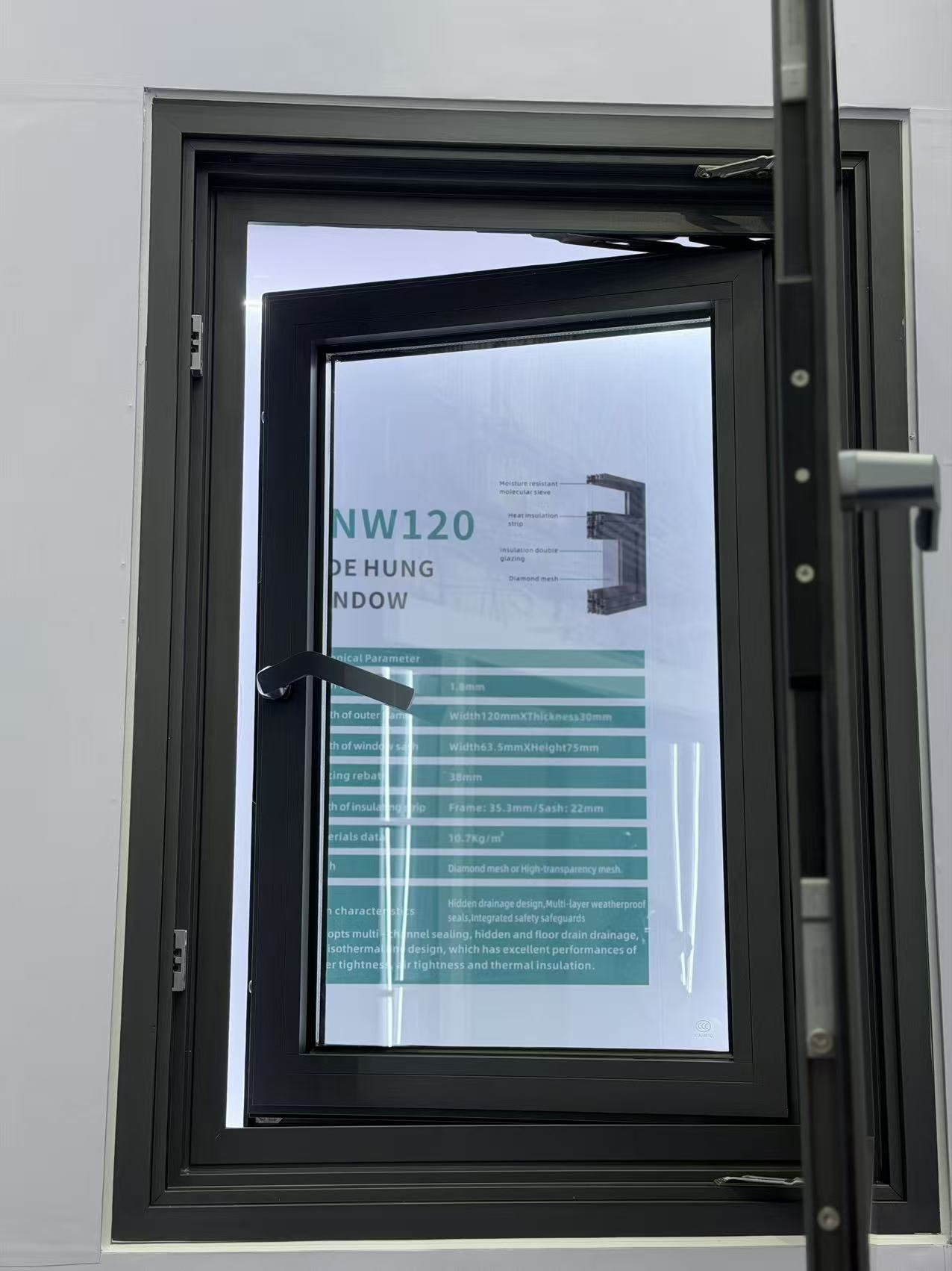
Which delivery term gives me better control over Decorative profile freight costs?
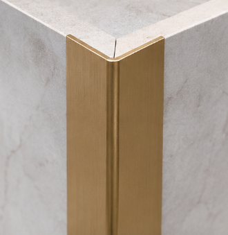
What low-carbon Awing window materials are gaining wider market acceptance?
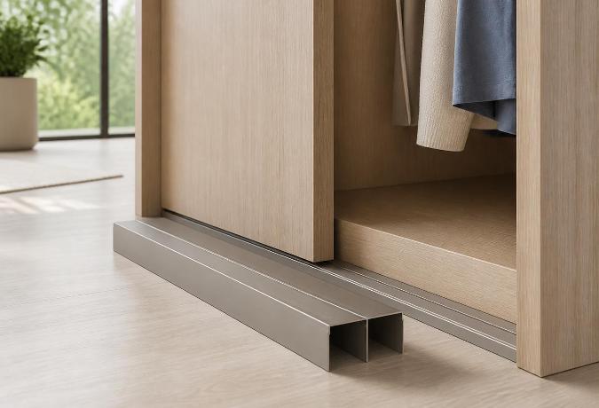
Why Sliding Door Track Geometry Determines Wardrobe Longevity
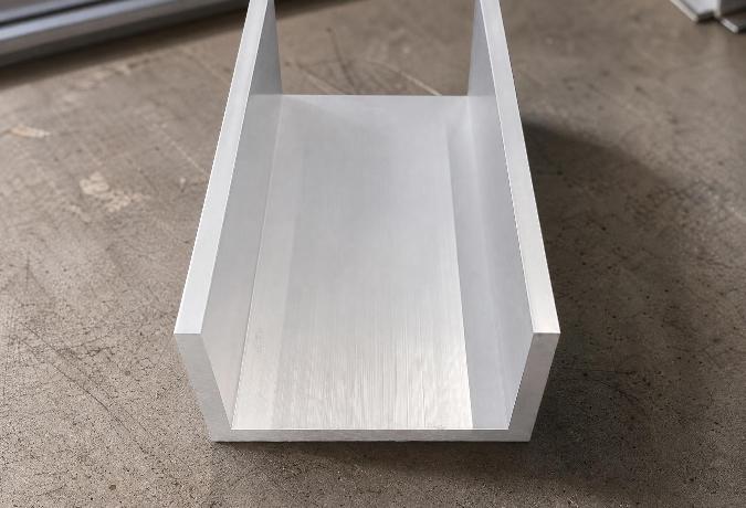
Engineering Mechanics and Surface Dynamics of Aluminium Channel Profiles
Understanding Aluminium Round Tube Specifications for Structural Engineering
Why the 90-Degree Angle in Standard Aluminium Profiles Determines Structural Reliability
How can I ensure a Floding door sample matches the planned mass production?
Why Mullion Thickness Determines How Much Glass an Aluminium Curtain Wall Can Actually Hold
Engineering Dimensional Stability in Aluminium Extrusions for Channel Profiles
Engineering the Structural Framework: The Mechanics of Aluminium Profiles for Kitchen Cabinets
Choosing an Aluminium Profile Supplier: What Actually Separates the Reliable Ones from the Rest
Can Awing window orders ship in batches to avoid project delays?
What response time should I expect for Awing window warranty claims?
Navigating the Supply Chain: Evaluating an Aluminium Profile Manufacturer for B2B Procurement
Engineering Structural Integrity Through Precision L-Shaped Aluminium Profiles
Thermal Dynamics in High-Power Electronics: Engineering Aluminium Heatsink Profiles
Why the T-Slot Design Determines the Real Strength of Structural Aluminium Extrusions
How long should replacement Sliding window parts remain available after purchase?
Should I expect volume discounts when reordering the same Sliding window model?
The Multi-Strip Sealing Structure Inside Aluminium Windows and Doors
Why the Frame Width on an Aluminium Sliding Door Determines Your Room’s Light
The Engineering Behind Decorative Aluminium Profiles: Alloys, Surface Treatments, and Edge Protectio
What alternative materials could make Casement doors more resilient and recyclable?
How can I compare Awing window quotes without missing hidden packing costs?
Decoding Structural Tolerances in Aluminium Extrusion Profiles for Channel Applications
Engineering an Aluminium Square Tube for Modern Structural Integrity
Engineering Tolerances and Alloy Mechanics in Extruded Aluminium Construction Profiles
The Engineering Mechanics Behind Aluminium Angle Profiles in Modern Construction
Can an Industrial profile be modified for my assembly without weakening it?
What warning signs suggest a Sliding door seller may disappear after payment?
What energy-efficient alternatives to Casement doors are worth comparing now?
Can a Casement window handle temperature changes without seal failure?
Who pays for unloading and destination handling under Casement door CIF terms?
Custom Aluminium Extrusion Profiles: The Engineering Mechanics of T-Slot Frameworks
Material Transitions and Geometric Stability in Decorative Aluminium Profiles
Can I negotiate a lower Sliding door MOQ for a showroom launch?
Key Advantages of Using Structural Aluminium Extrusion Profiles in Construction
What evidence shows an Awing window factory manages coating waste properly?
How can I protect my deposit when ordering custom Decorative profile?
How do I spot unusually low Industrial profile prices before committing funds?
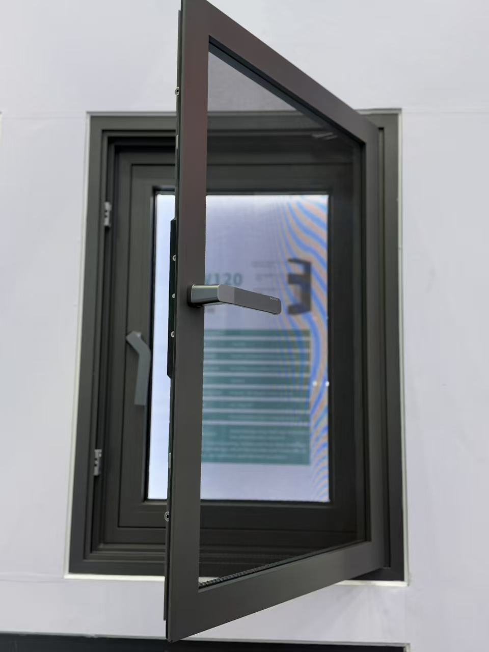
How can I check that a Shutter supplier is not using unapproved subcontractors?
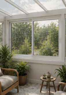
What contract terms protect my Casement door drawings and branding?
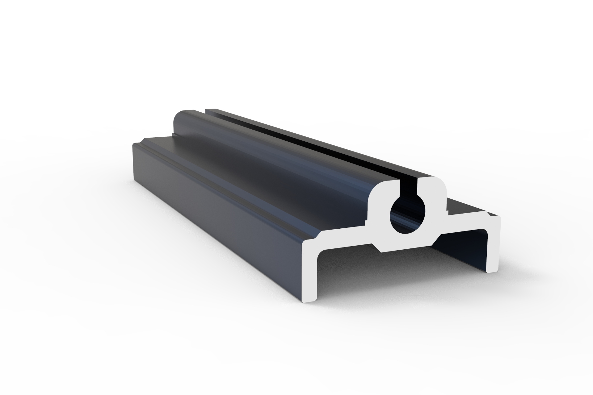
How can I compare Casement door insulation ratings before placing an order?
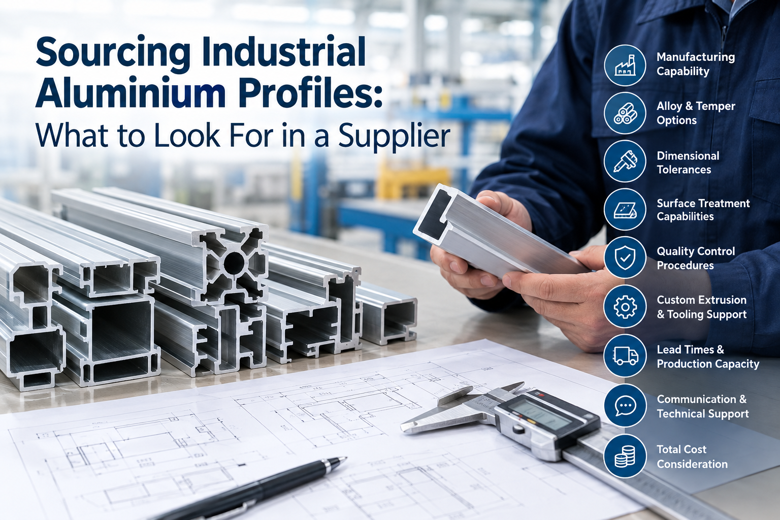
Sourcing Industrial Aluminium Profiles: What to Look For in a Supplier
How do I keep ownership of a custom Architecture profile extrusion die?
The Energy Efficiency Benefits of an Aluminium Frame Sliding Glass Window
How do I check Industrial profile alloy grades against the shipping documents?
What Casement window warranty period is reasonable for an overseas buyer?
How are defective Sliding window units usually replaced internationally?
How can I reduce breakage risks when shipping Casement windows overseas?
The Structural Mechanics Behind Decorative Aluminium Profiles
How Do Engineers Select Industrial Aluminium Profiles for High-Load Frameworks?
What payment structure reduces my risk on a first Industrial profile order?
Should I approve a Casement window sample before checking its hardware strength?
Structural Mechanics of Channel Extrusions in Architectural Aluminium Profiles
Engineering Mechanics of Aluminium Extrusion Profiles in Channel Systems
What functional tests should I perform on a Sliding door prototype?
What payment terms are fair when Decorative profile colors remain unconfirmed?
Is a letter of credit practical for a large Casement window shipment?
How should Industrial profile bundles be packed to prevent transit damage?
Which safety documents should I request for Awing window imports?
What shipping delays commonly affect Architecture profile orders during peak season?
How to Specify Extruded Aluminium Profiles: Costs, Alloys, and Tolerances
Is a Floding door suitable for a wide opening exposed to strong winds?
Structural Integrity in Modular Design: Engineering T-Slot Aluminium Extrusion Profiles
Resolving Corner Stress: The Engineering Mechanics Behind Aluminium Profiles in Architectural Framin
How do Floding door prices change with glass, hardware, and finish choices?
How can I prove Shutter defects remotely without returning every unit?
How can I shorten Awing window sampling without losing critical tests?
Does ordering mixed Shutter sizes usually change the unit price or MOQ?
How should Industrial profile warranty responsibility be shared after assembly?
How should I plan Shutter inventory when ocean freight schedules change?
How do escrow arrangements reduce risk for a new Floding door supplier?
What frame materials make a Sliding window last in harsh coastal weather?
How can I verify that a Shutter certificate matches the actual product?
Can automated Shutters replace manual systems without raising lifecycle costs?
How do I choose the right Casement window size for a windy building?
What should an ethical audit cover at a Decorative profile factory?
How should I document Industrial profile defects before disputing the final payment?
Are lightweight Industrial profile alloys reliable enough for demanding machinery?
Are thermal-break casement windows becoming a better long-term choice than standard frames?
What is a realistic MOQ for custom sliding windows without pushing up unit cost?
What casement window specs should I compare for windy and rainy project sites?
Are there better material options for sliding windows if aluminum prices rise?
How do I ensure aluminum casement windows can handle extreme coastal winds?
What is the typical minimum order quantity for commercial sliding windows?
Are there energy-saving alternatives to sliding windows that reduce material and maintenance costs?
Are energy-efficient Awing windows a practical alternative for reducing long-term building costs?
What alternatives to traditional sliding doors can lower costs without sacrificing durability?
What alternatives to industrial profiles can reduce material costs without hurting strength?
Extruded Aluminium Profiles: Flexible Manufacturing for Diverse Customer Needs
Why Aluminium Curtain Walls Are Popular in Modern Architecture
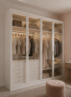
How do I choose a decorative profile that stays stable in humid or harsh environments?
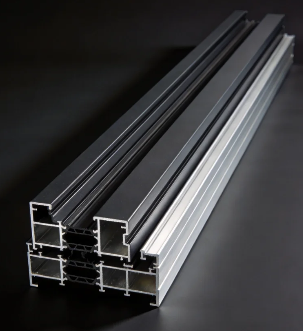
How do I choose an architecture profile that stays stable in harsh outdoor conditions?
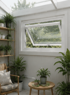
How can I compare Awing window specs to avoid poor performance in harsh weather?
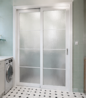
How can I compare Sliding door sizes and hardware ratings for harsh commercial environments?
How do I choose the right shutter specifications for harsh climates without overpaying?
What eco-friendly alternatives to folding doors can cut costs without hurting durability?
How do I choose the right shutter specifications for harsh weather without overpaying?
What eco-friendly casement door materials can lower costs without hurting durability?
What newer materials can replace industrial profiles without raising costs or supply risks?
How do I choose a decorative profile that stays stable in humid, high-traffic spaces?
What sustainable material alternatives can replace aluminum architecture profiles?
What should I check in Awing window specs to ensure reliable performance in harsh weather?
How can I compare Sliding door sizes and thermal ratings for harsh climates before buying?
What newer materials can replace aluminum in awning windows without raising our costs?
How do I choose the right Sliding door specs for smooth operation in harsh environments?
How do I choose a folding door that stays stable in harsh weather and heavy daily use?
How can I choose the right shutter specifications for harsh weather and long-term use?
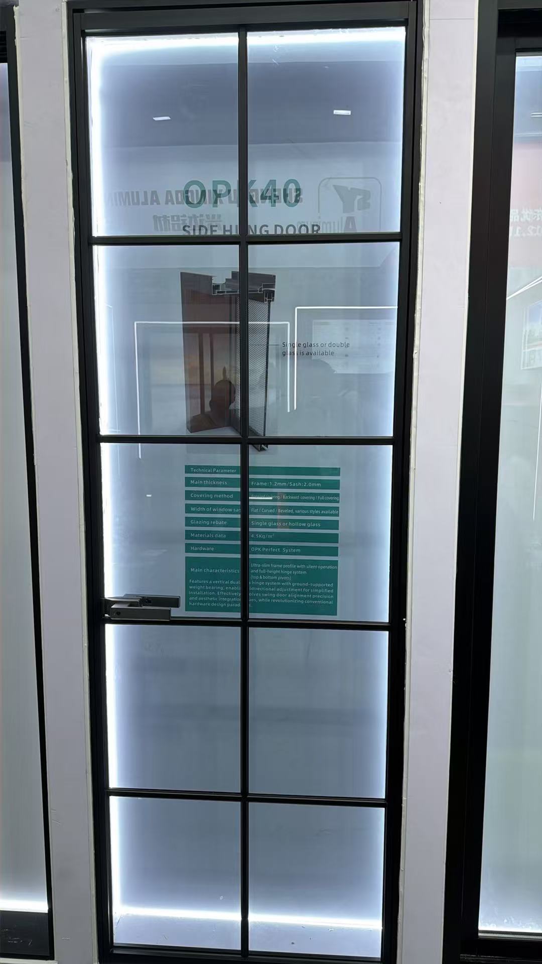
How do I compare casement door U-values, hardware, and weather sealing before buying?
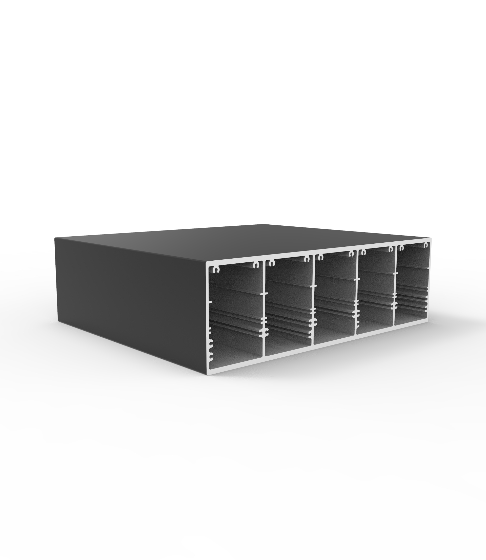
How do I choose the right industrial profile size for strength and load needs?
How do I choose the right shutter specifications for harsh weather and long-term commercial use?
How do I choose the right Casement door size and hardware for harsh weather?
What greener alternatives to decorative profile can cut costs without hurting durability?
What lower-cost, eco-friendly materials can replace decorative profiles?
What lower-carbon alternatives to aluminum architecture profiles are practical for our project?
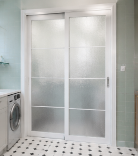
How can I compare sliding door systems for insulation, security, and long-term use?
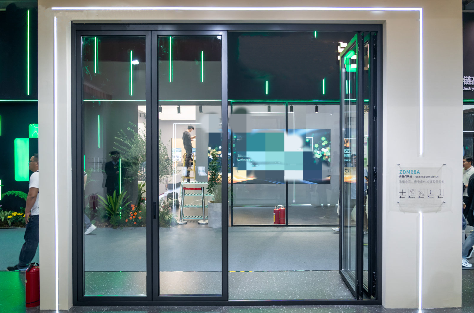
What is the standard production lead time for bulk orders of folding doors?
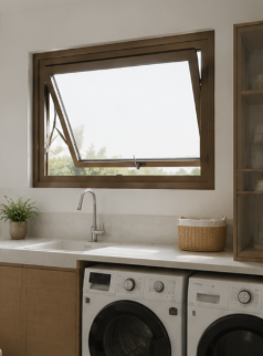
How do I choose the right Awing window size and glass specification for harsh weather?
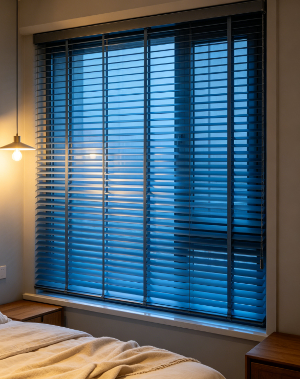
How can I test shutter samples so the final bulk order matches their quality and finish?
Can suppliers make custom double glass casement doors from my CAD drawings?
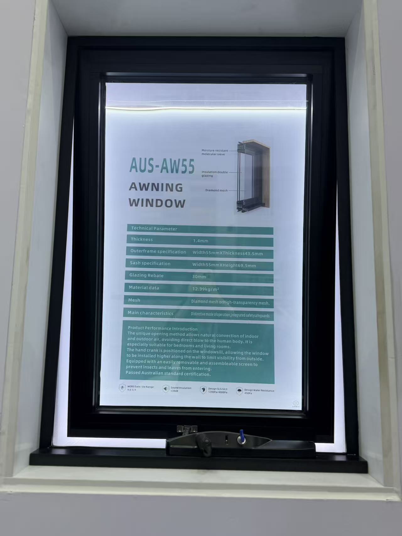
What safety certifications should I request when importing awning windows?
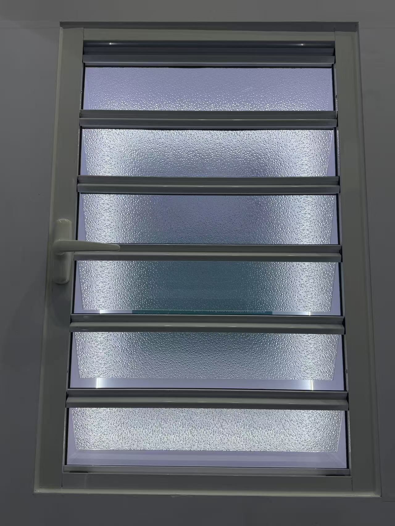
How long does it usually take a factory to make custom shutter samples?
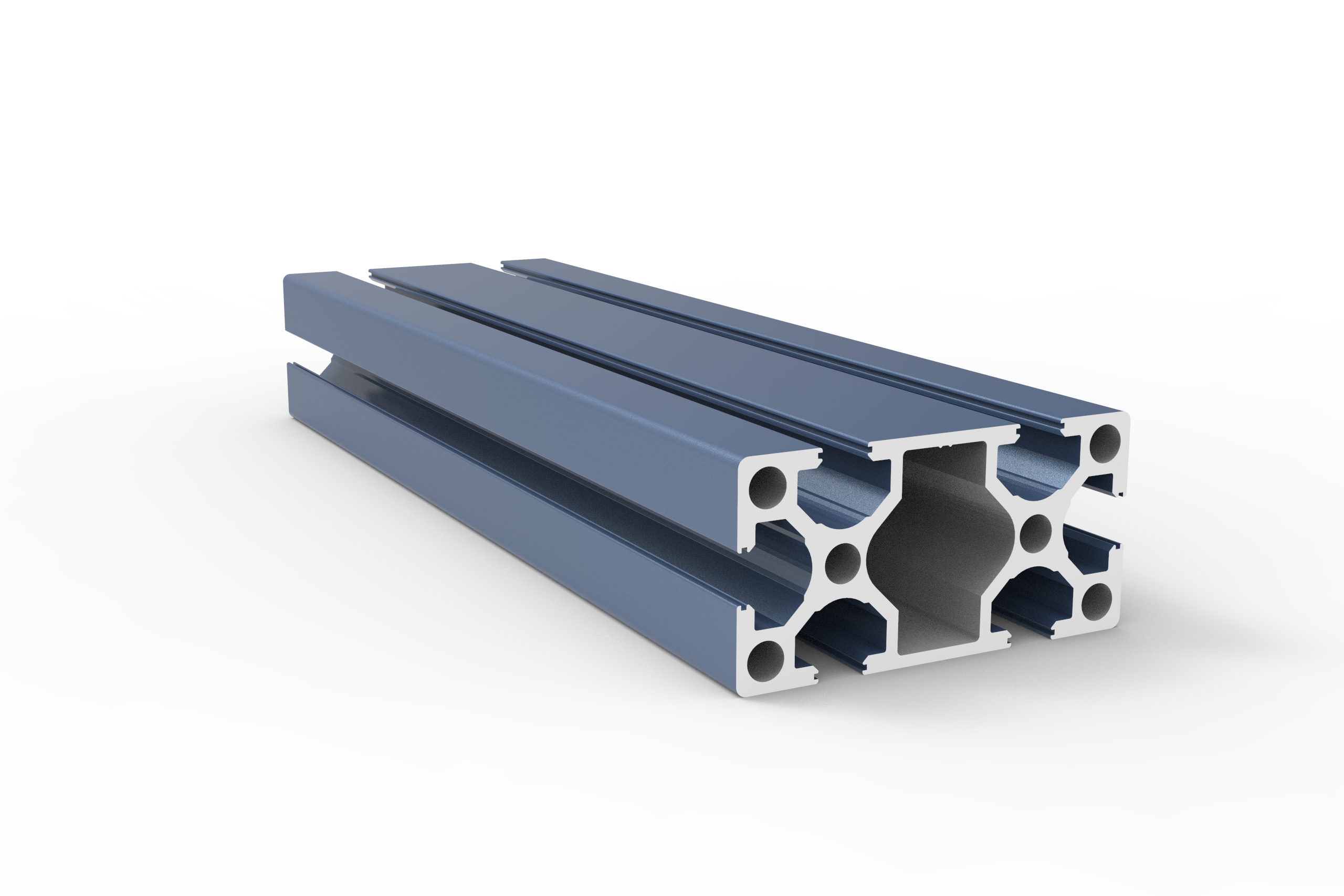
What T-slot industrial profile size is best for a heavy duty machine frame?
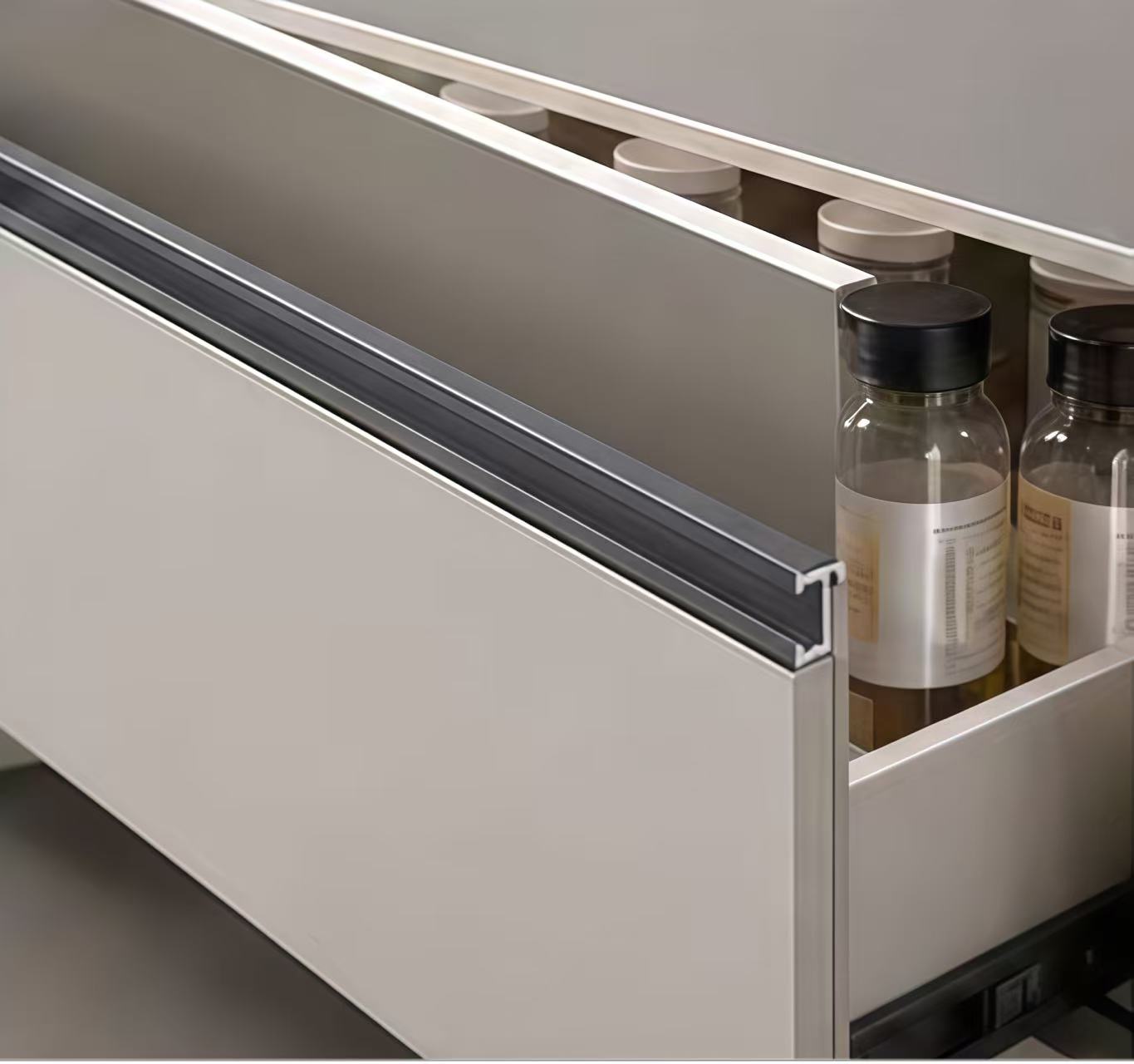
How do I choose the right stainless steel decorative profile for high humidity areas?
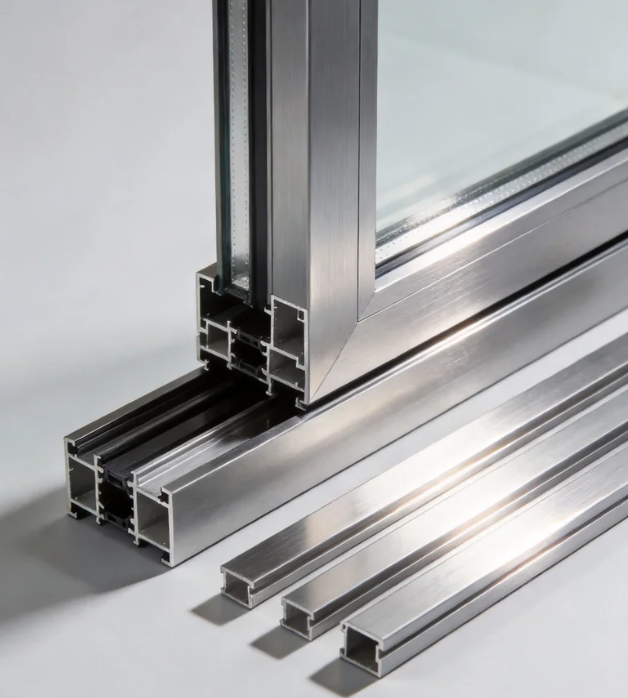
How do I choose the right aluminum architecture profile for coastal buildings?
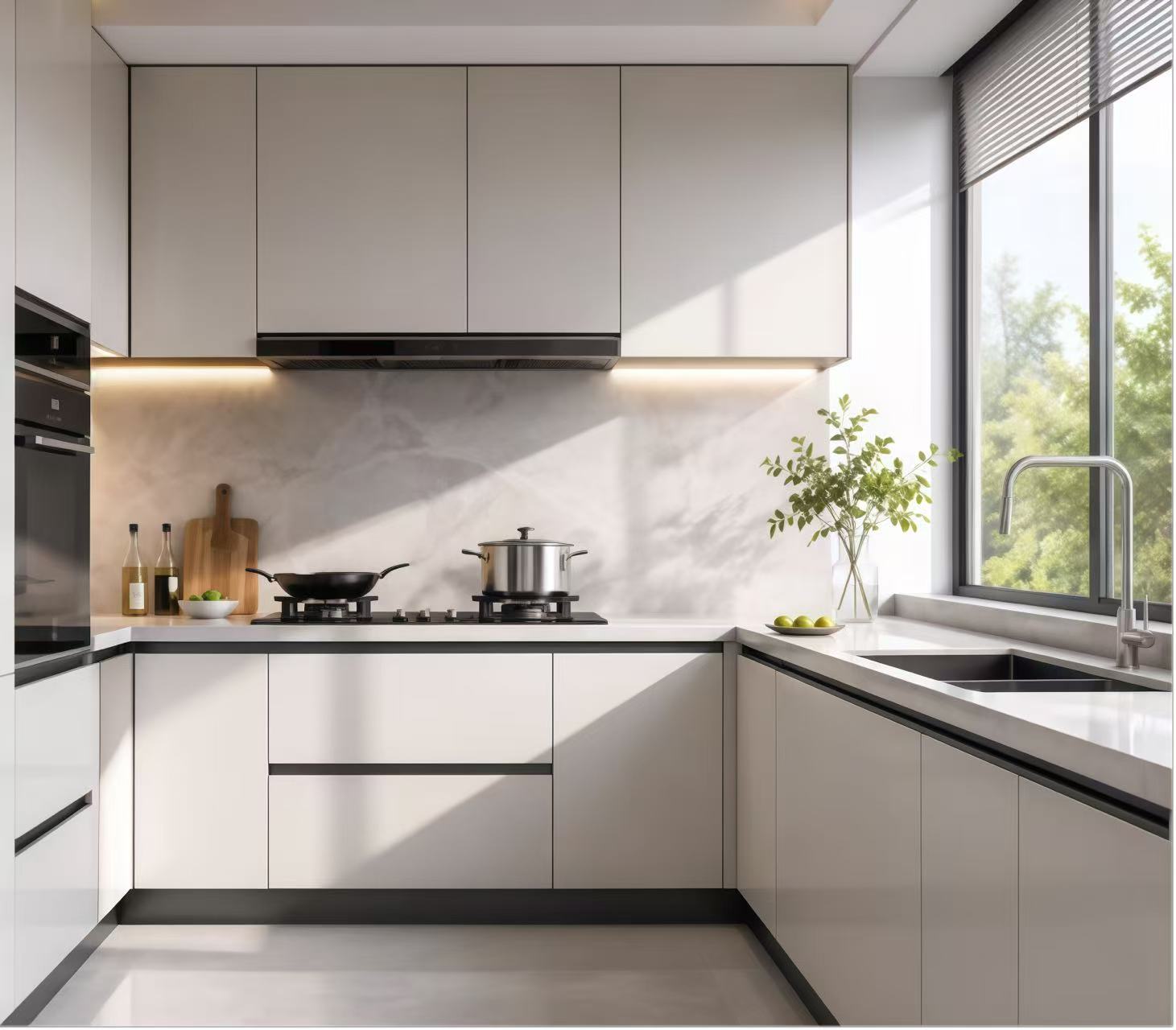
How do I choose the right stainless steel decorative profile for high humidity areas?
What wind load specs should I check for aluminum casement windows in coastal high-rises?
How do I know which aluminum industrial profile alloy is best for heavy machinery frames?
How do I choose the right alloy grade for aluminum architecture profiles?
How do I select the right heavy-duty hardware for exterior commercial floding doors?
How do I select the right glass thickness for bulk awing window orders?
What frame thickness is recommended for commercial aluminum casement doors?
What frame thickness is best for high-rise commercial sliding windows?
How to choose weather resistant aluminum floding door specs for commercial use?
How do I choose the best water tightness rating for commercial awing windows?
How do I choose the right frame material for commercial casement doors?
How do I choose the right wind load rating for sliding windows in coastal areas?
What is the best material for outdoor decorative profiles to prevent rust and fading?
How do I choose the right track thickness for high-traffic commercial sliding doors?
How do I choose between PVC and basswood shutters for high-humidity areas?
How do I choose between double and triple glazing for casement windows in cold climates?
How do I choose the right industrial profile thickness for heavy-duty cnc machine frames?
How do I choose the right alloy for outdoor architecture profiles to prevent corrosion?
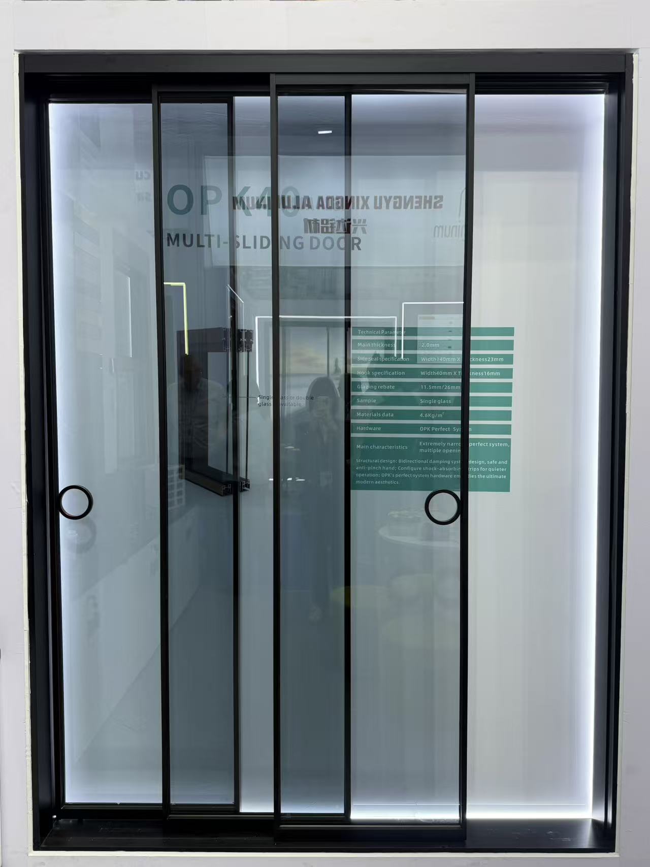
Can you design a slim frame profile for modern minimalist look?
How do I choose the right wind-resistant floding door for a coastal commercial building?
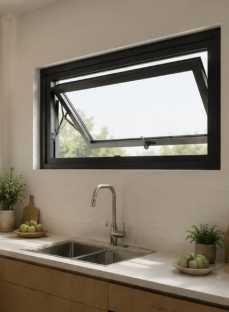
What key specs ensure a casement window can withstand heavy rain and high winds?
How do I choose the right aluminum alloy grade for heavy-duty industrial profiles?
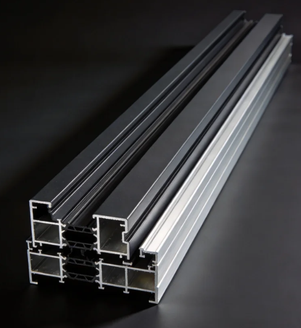
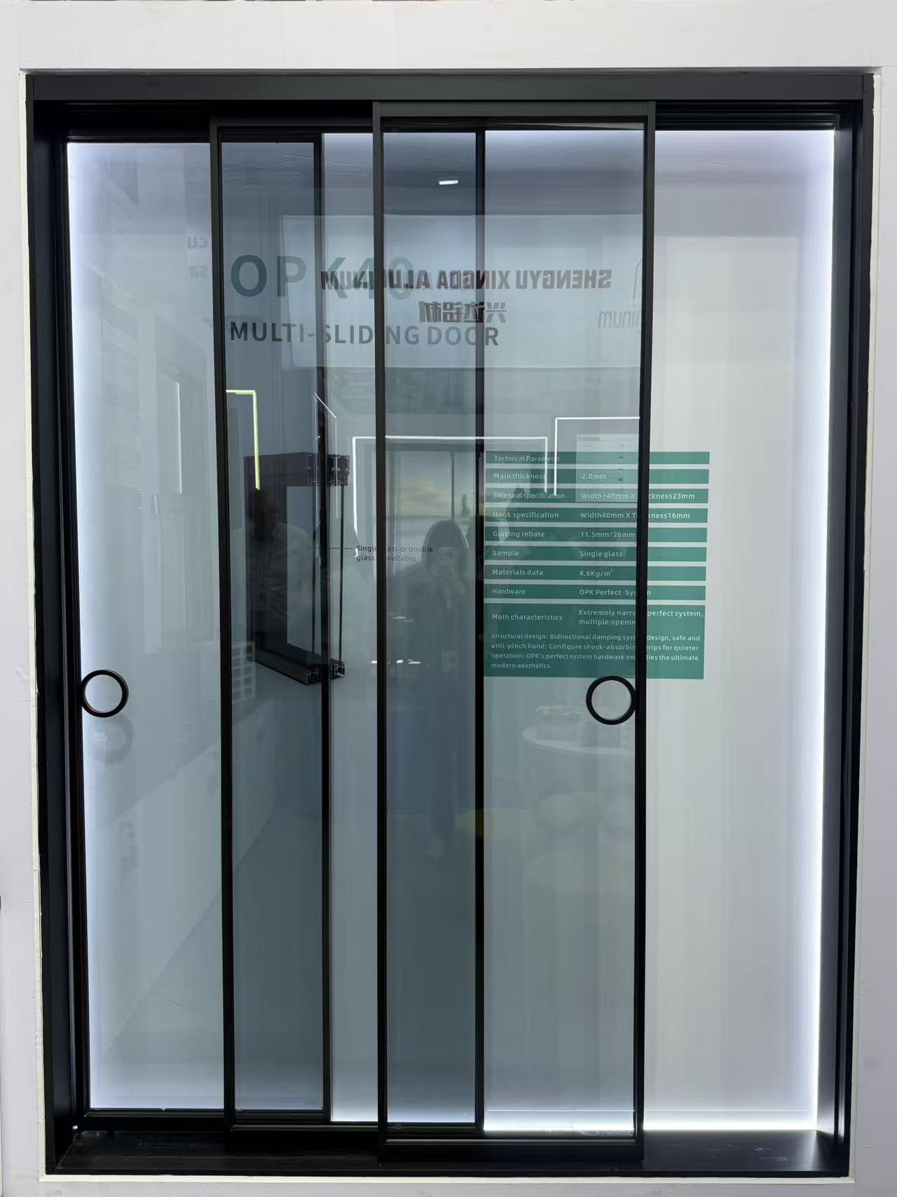
Which alloy grade of architecture profile is best for coastal areas to resist rust?
How do you pack windows to prevent glass breakage in transit?
Are slim-frame thermal break systems replacing traditional ones?
Does the price include the matching frame and installation kit?
How do you protect our proprietary design drawings from leaks?
How do I choose the right decorative profile for high-traffic hotel lobbies?
Is your factory the actual manufacturer or a trading partner?
Is it possible to 3D print a prototype before cutting steel?
Do you outsource any part of the painting process to others?
How do you handle replacement parts for damaged track rollers?
Do you accept escrow payments through third-party platforms?
Do you have ISO 9001 certification for your production line?
Are there extra fees if we pay via bank telegraphic transfer?
What is the price difference between powder coat and anodized?
What is the warranty period for the lock and hinge hardware?
What is your policy for dimensional deviations in the batch?
What happens if the shipment is delayed due to factory error?
Do you offer online technical support if color fading occurs?
Is it possible to engrave our brand logo on the tension screw?
Do you offer credit terms for long-term purchasing partners?
Can you palletize the shipments for easy forklift unloading?
What are the latest eco-friendly finish trends for decorative profiles in modern interior design?
What are the tooling cost and design limitations for customizing heavy-duty industrial profiles?
Has your architecture profile manufacturing facility passed ISO 9001 certification?
Can we use Alibaba Trade Assurance for our initial sliding door order to mitigate risk?
Do you provide free corner samples of the casement window frame for color verification?
Is it possible to custom-match a specific RAL color for a decorative profile order?
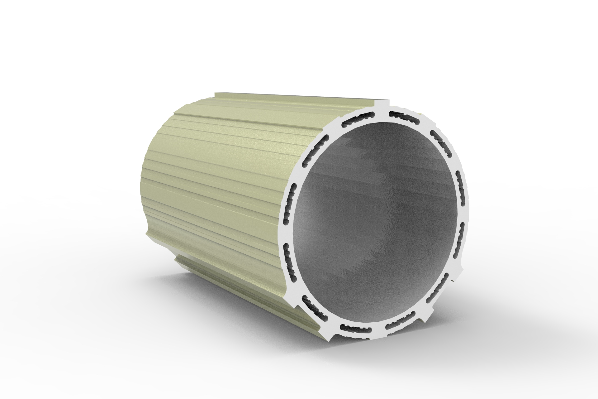
Can I request a 3D-printed sample before ordering a custom industrial profile mold?
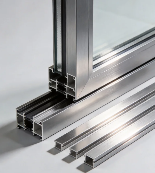
Can you extrude an architecture profile based on our proprietary CAD drawings?
What thermal performance certifications does a sliding door need for the UK market?
How are heavy floding door panels crated to ensure safe unloading at the job site?
Can we arrange our own freight forwarder to pick up the casement door shipment FOB?
What is the estimated ocean freight transit time for a shutter shipment from China to Europe?
How can we source replacement seals for your awing window models in the future?
How are sliding windows typically packaged to prevent glass breakage during ocean transit?
What is the average lead time for a 40ft container of standard aluminum casement windows?
Are there any extra tooling fees if my decorative profile order doesn’t meet the MOQ?
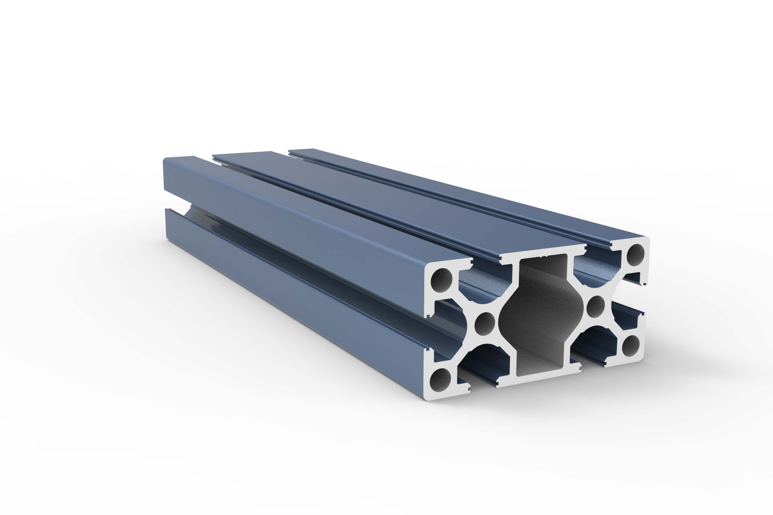
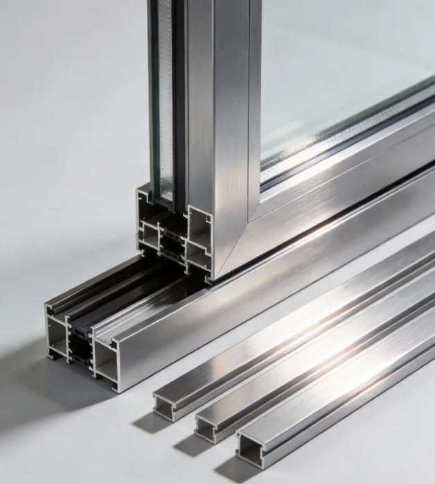
Can I get 3D printed prototypes of custom architecture profiles before committing to mold tooling?
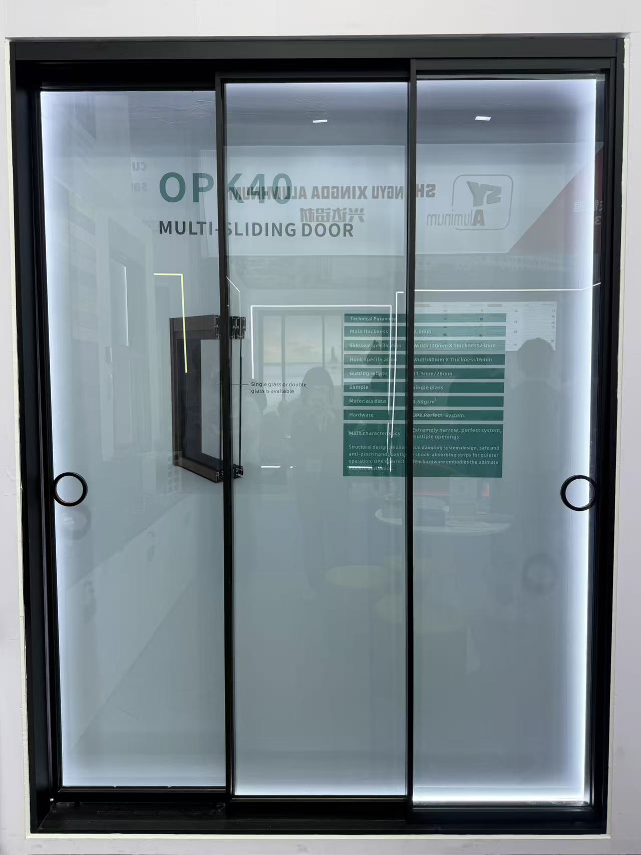
How is smart glass technology being integrated into modern residential sliding door units?
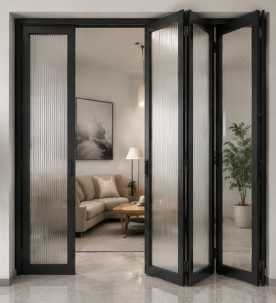
What options do you have for customizing the threshold height of an aluminum floding door?
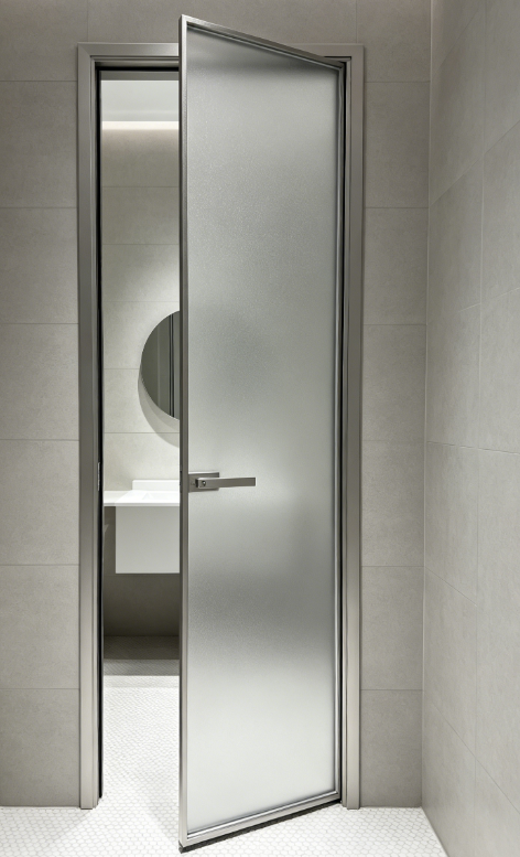
What thermal break technology should I look for in a heavy-duty aluminum casement door?
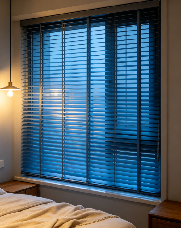
What quality control processes do you perform on shutter hardware before final assembly?
Do you offer DDP shipping terms for awing window orders delivered to our warehouse?
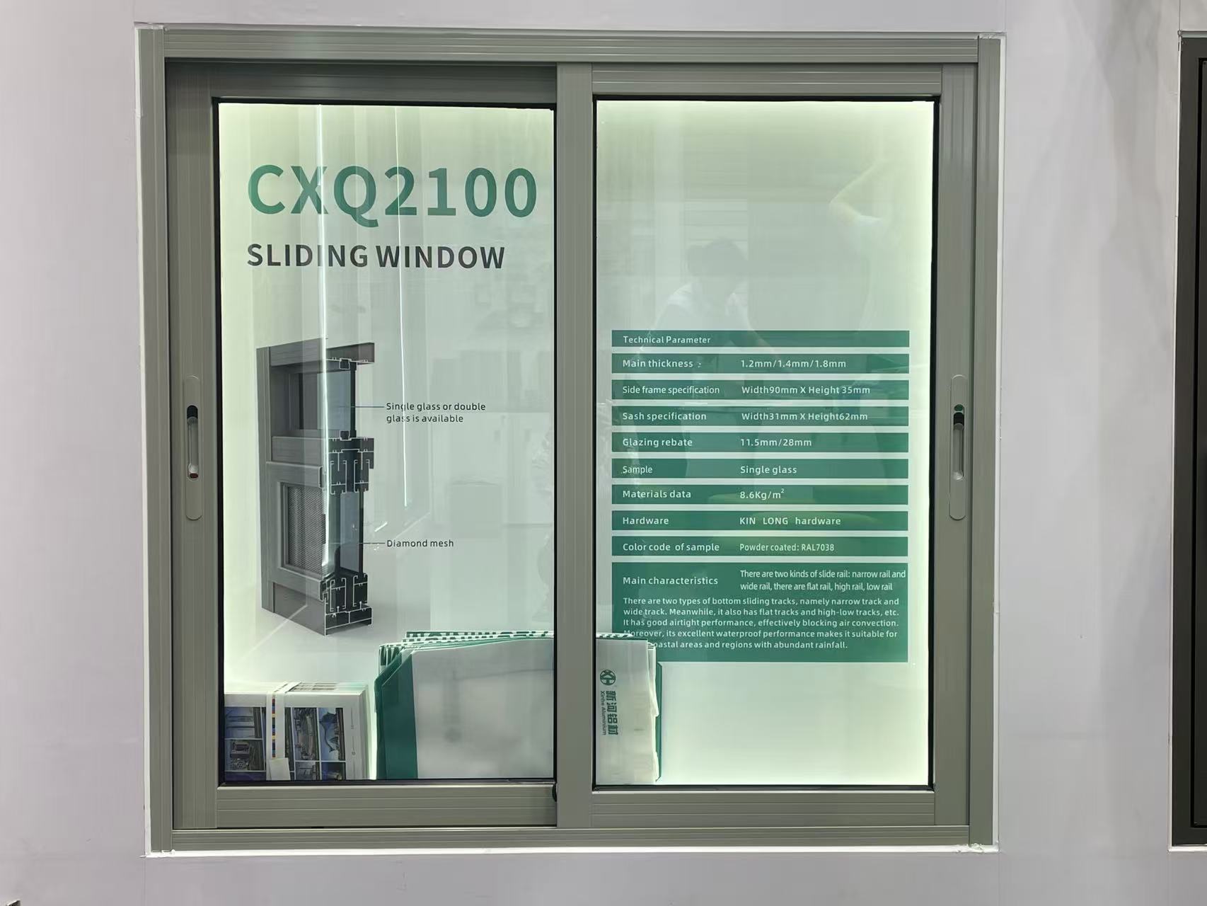
Is it possible to order a fully functional sliding window sample for mock-up testing?
Do you provide replacement hardware if the casement window hinges fail within 5 years?
How do you handle claims for decorative profile items damaged during transit?
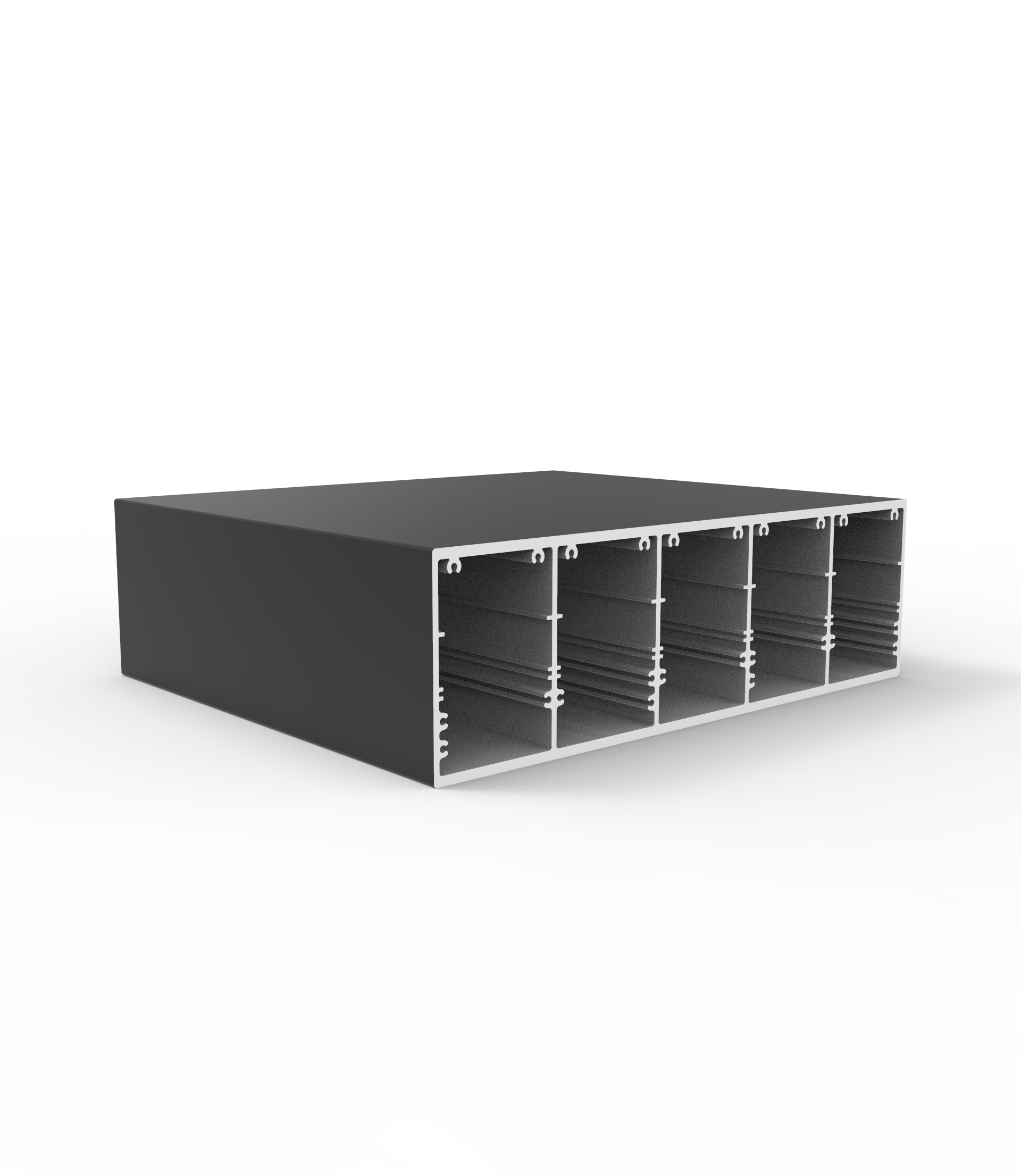
What is the standard MOQ for custom-extruded aluminum industrial profile orders?
How does the order volume affect the per-ton price of custom architecture profile designs?
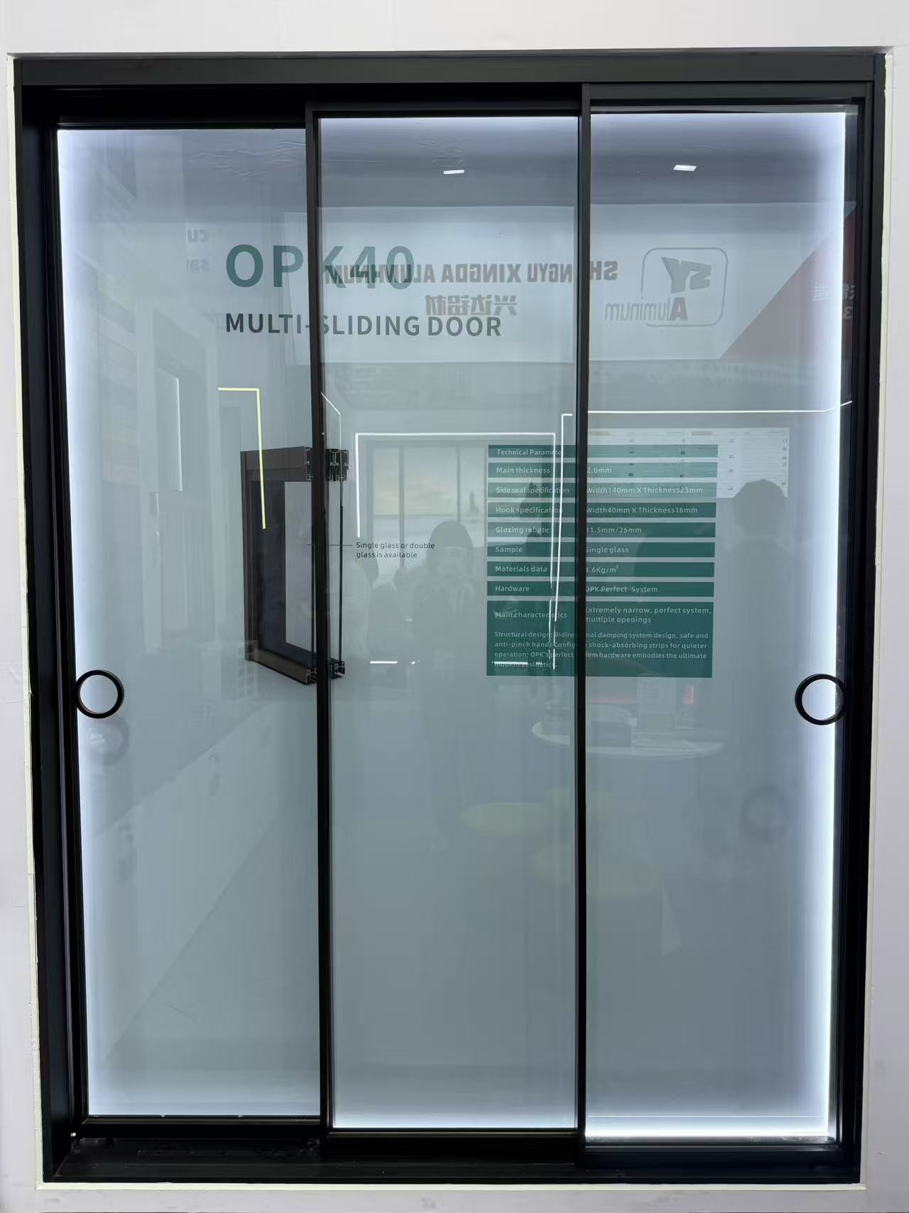
What is the warranty period for the rollers and tracks on your heavy-duty sliding doors?
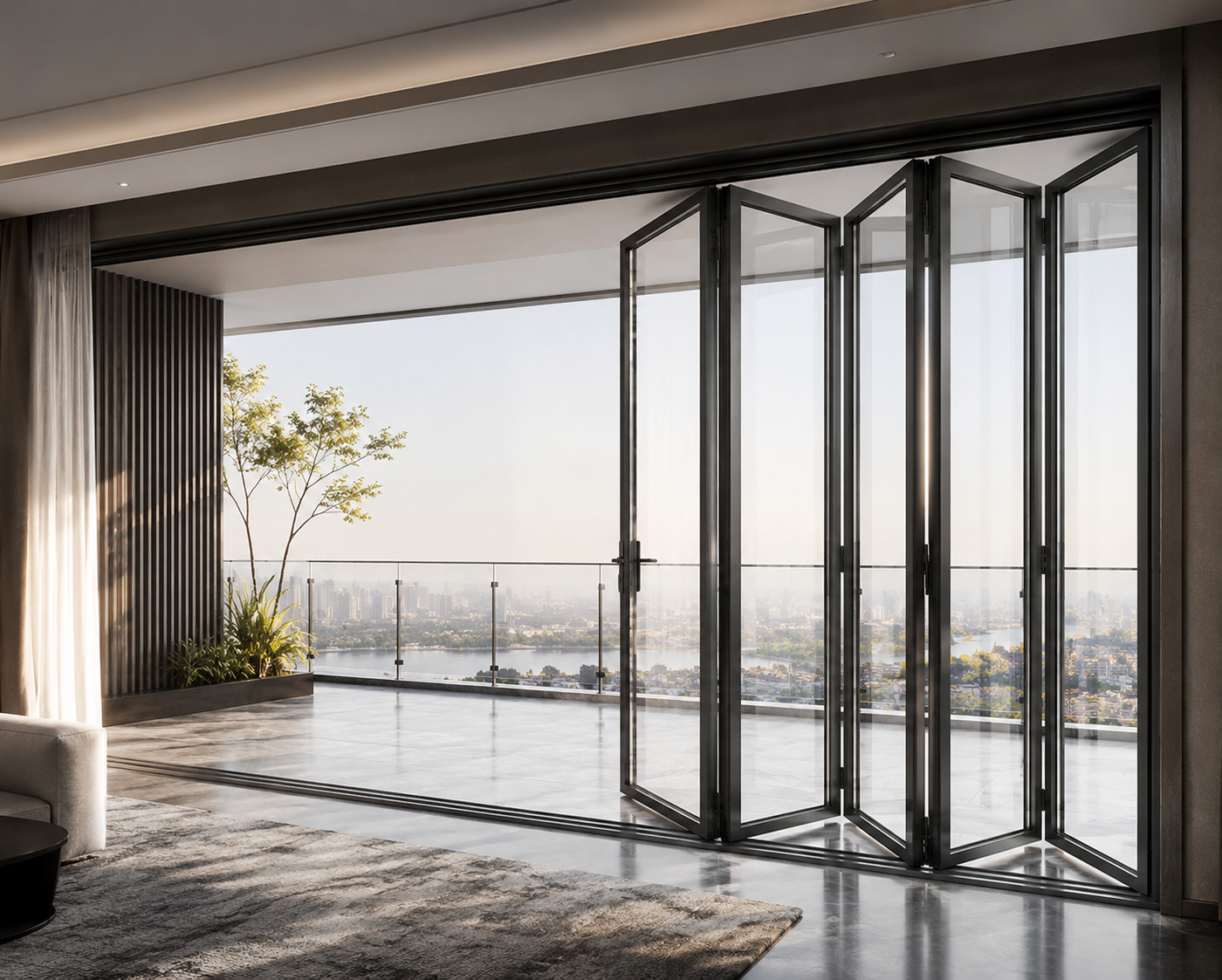
How can we secure our deposit when purchasing high-value custom floding doors from a new supplier?
Can your factory match custom anodized colors for decorative profiles based on physical samples?
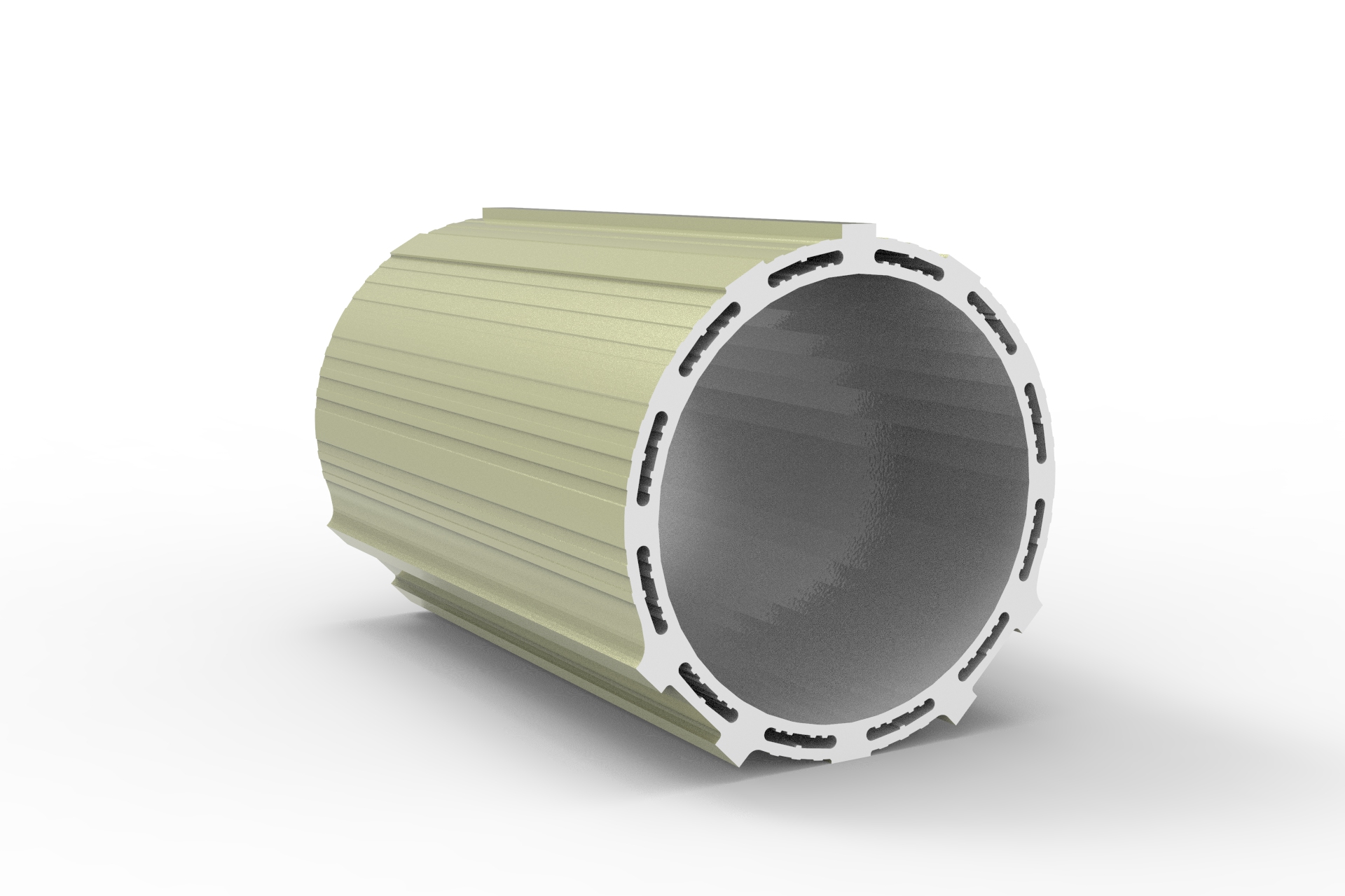
Is there a lighter alternative to aluminum industrial profile structures for robotics?
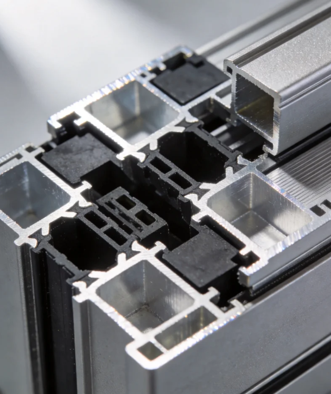
What payment security measures do you have for custom architecture profile tooling fees?
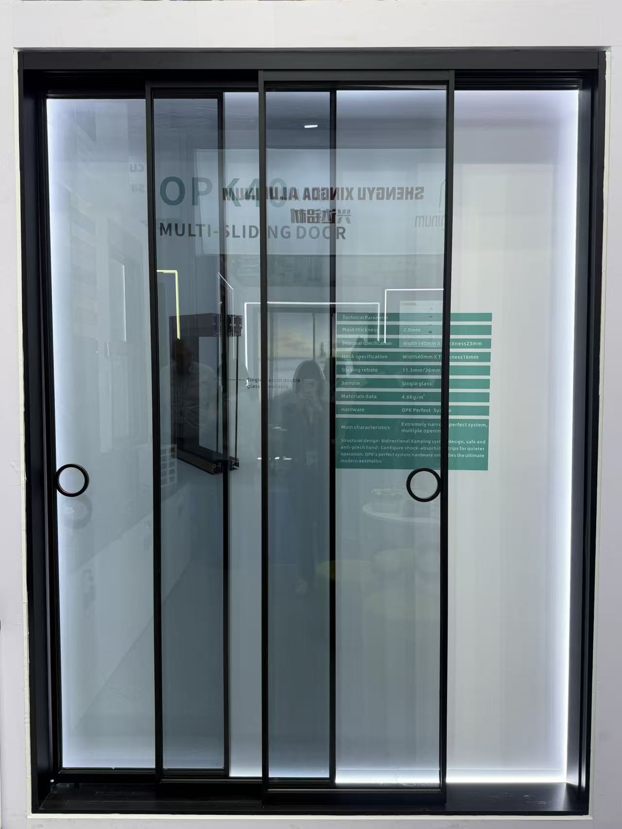
Can I order a sliding door with custom grid patterns between the glass panes?
How do you protect buyers against financial loss if the floding door shipment is delayed?
Are slim-frame aluminum casement door designs becoming more popular in modern offices?
What is your policy for replacing shutter components that arrive with color mismatch?
What kind of remote technical support do you offer for sliding window installation?
What is the maximum safe size for a top-hung awing window in commercial projects?
What environmental management standards does your decorative profile plant follow?
What is the standard lead time for producing a 40ft container of casement window orders?
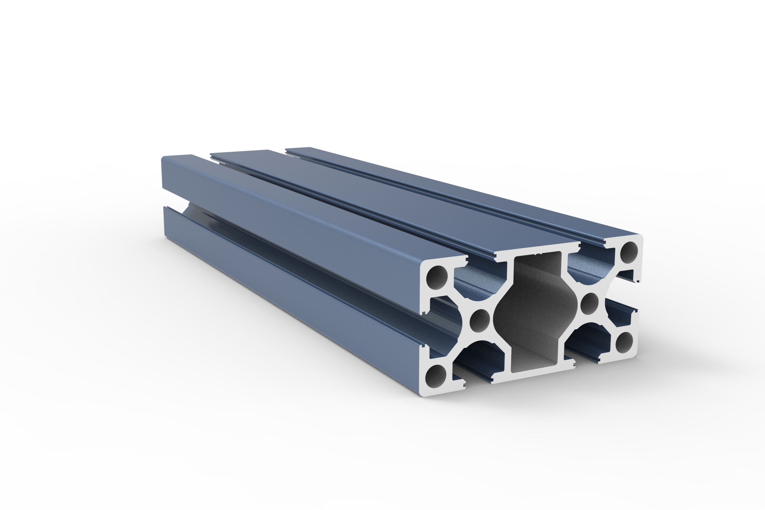
What is the warranty period for the anodized finish on your industrial profile?
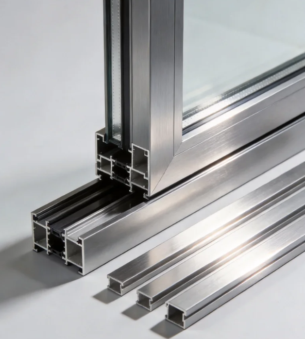
What are the latest eco-friendly trends in architecture profile manufacturing?
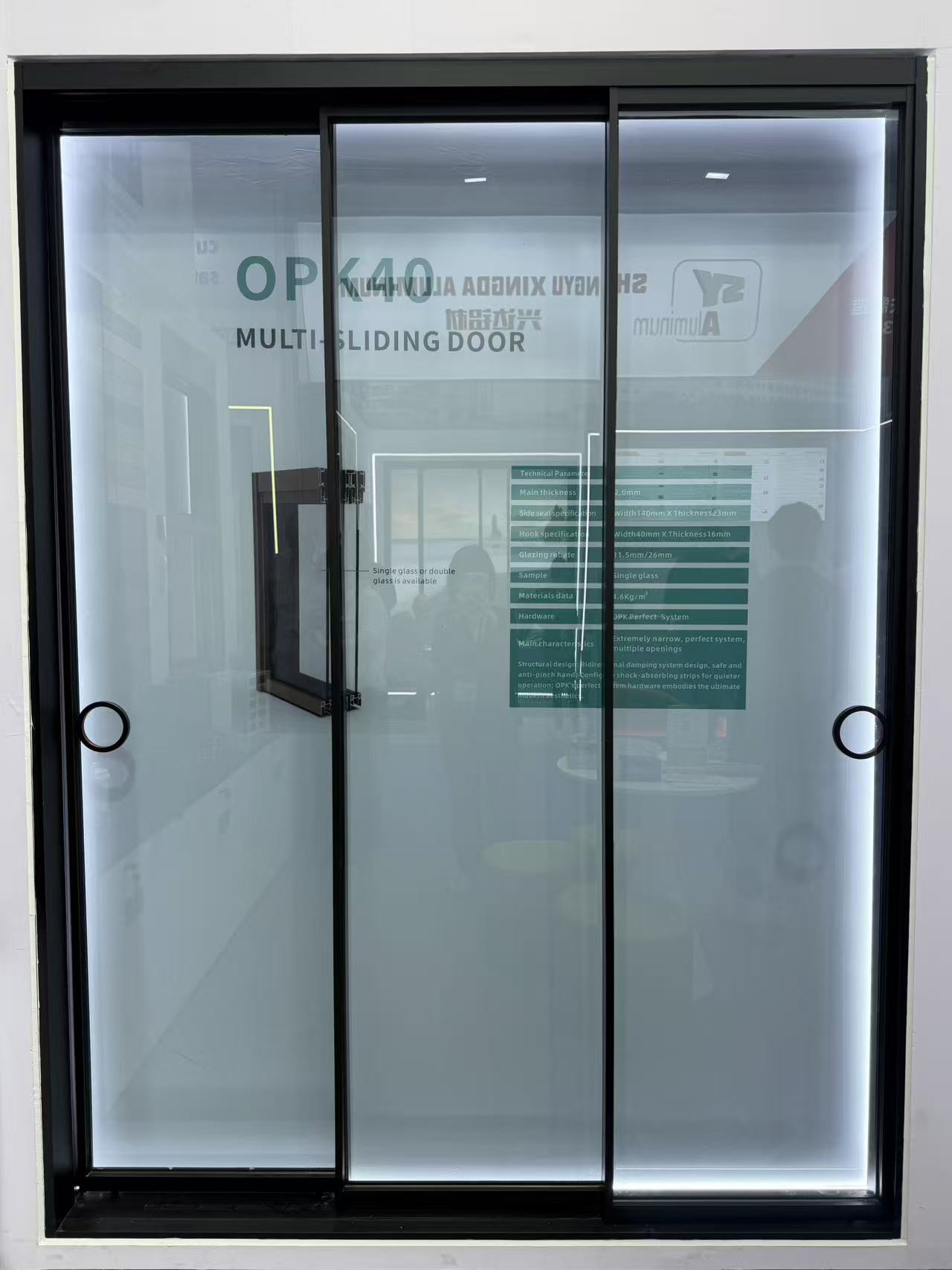
What is the average wholesale price per square meter for double-glazed sliding door systems?
How do I calculate the structural load requirement for a 5-panel exterior floding door?
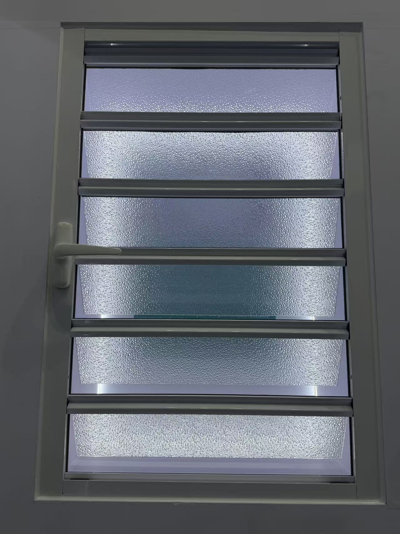
Do your exterior shutter systems comply with Florida building codes for hurricane protection?
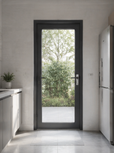
Do you offer Letter of Credit (L/C) payment options for casement door bulk orders?
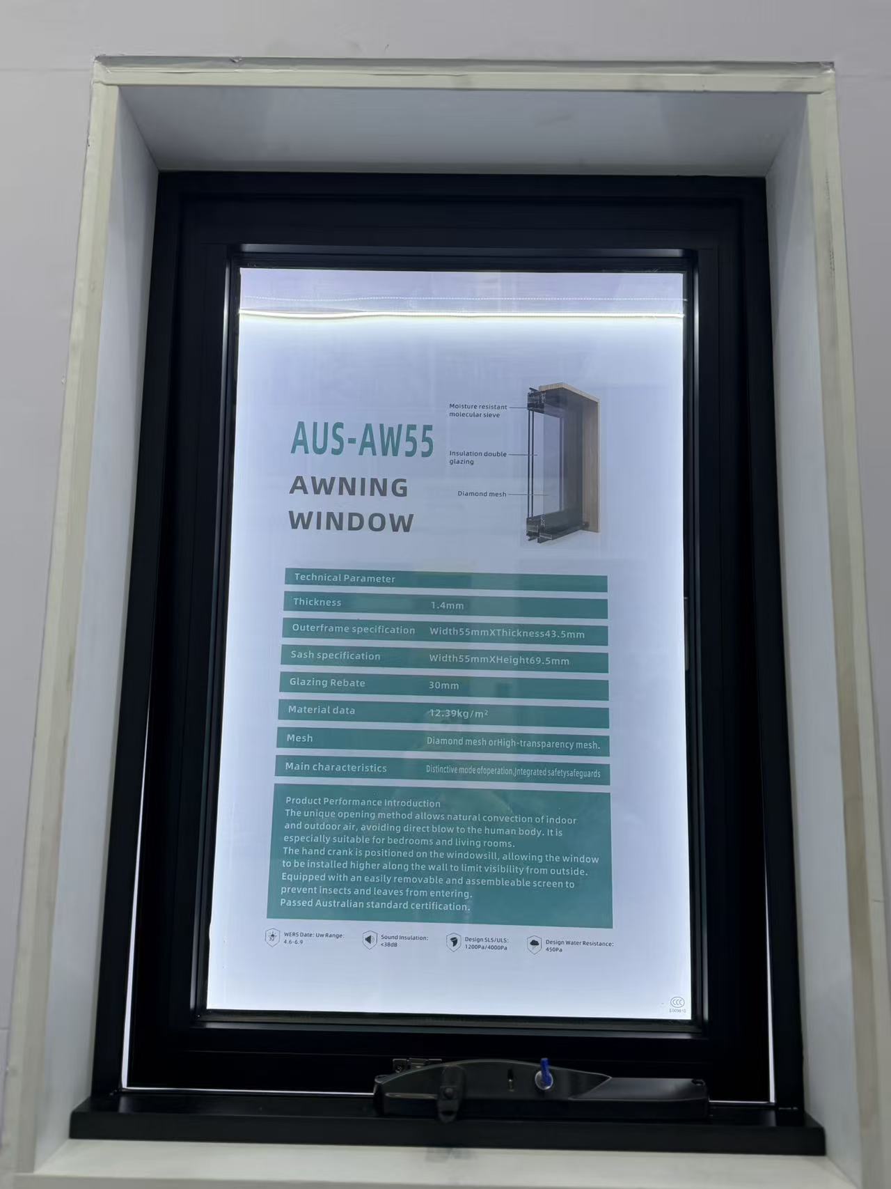
Which water tightness certifications are required for importing an awing window to Europe?
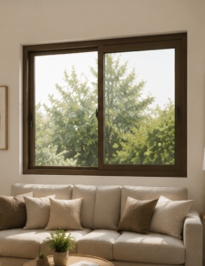
Do you allow virtual factory tours to inspect the sliding window assembly line?
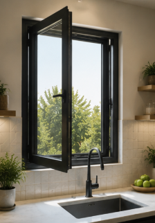
What is the typical MOQ for ordering standard-sized aluminum casement window units?
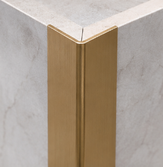
How long does it take to receive a physical sample of a gold-anodized decorative profile?
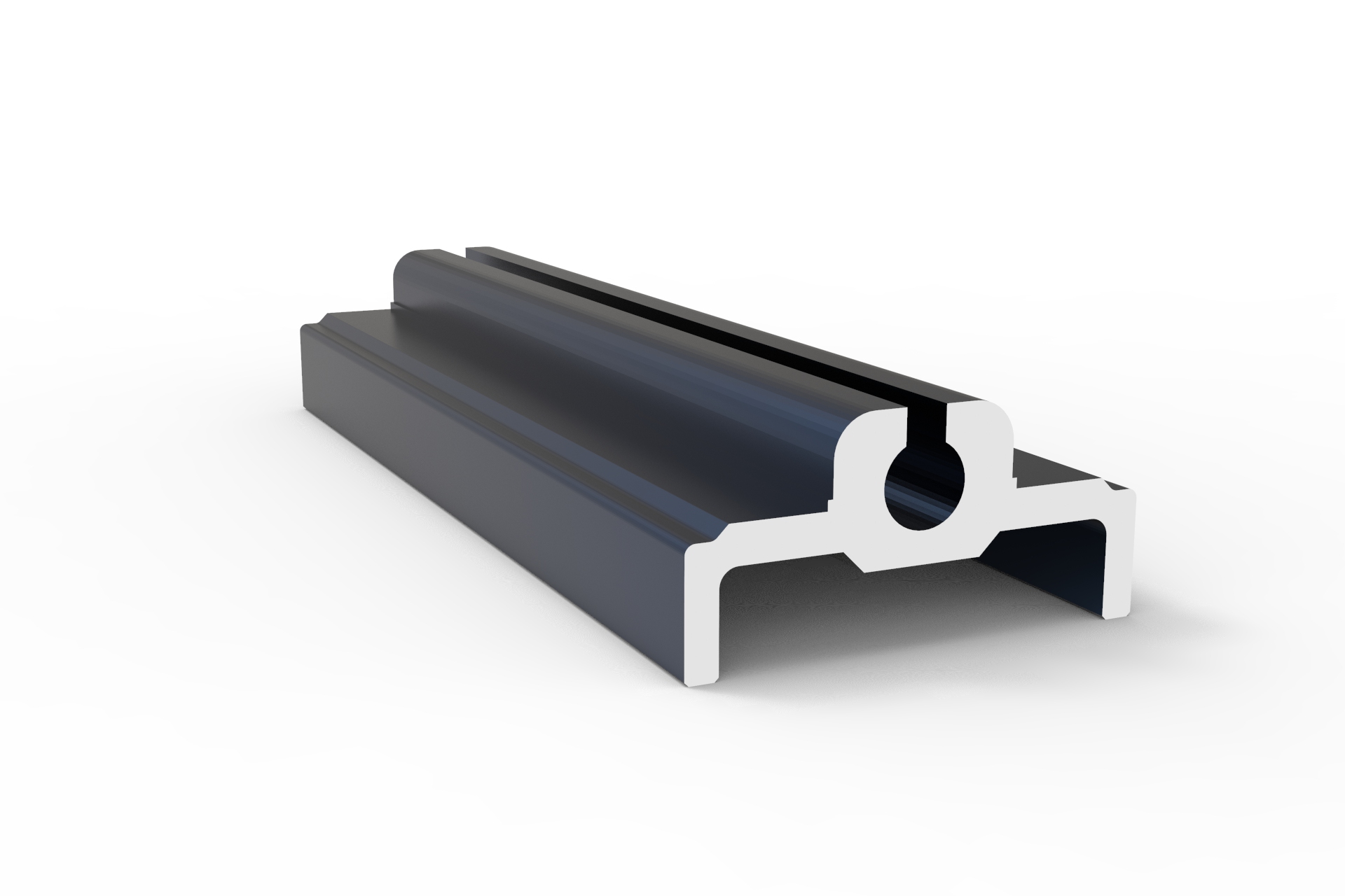
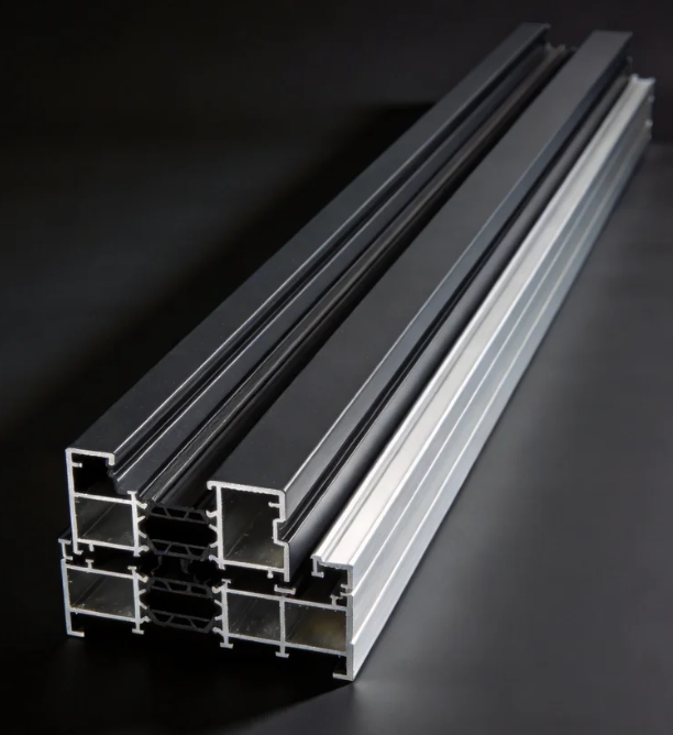
How do I choose the right alloy grade for architecture profiles in high-rise coastal buildings?
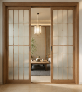
How do I choose the right track and roller specs for heavy-duty commercial sliding doors?
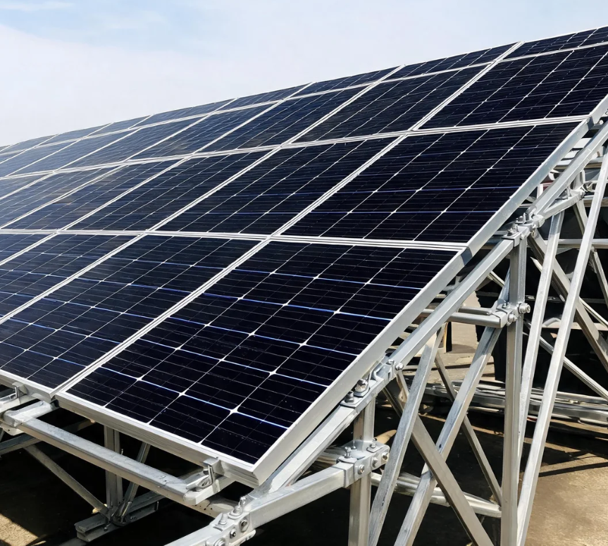
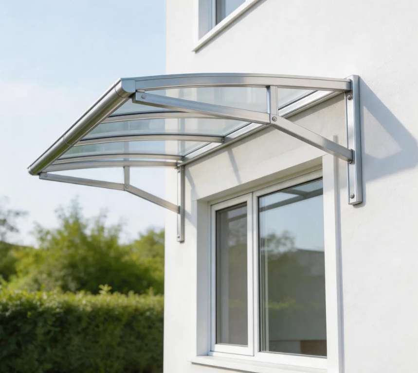
The core advantages of using aluminium profiles for the canopy
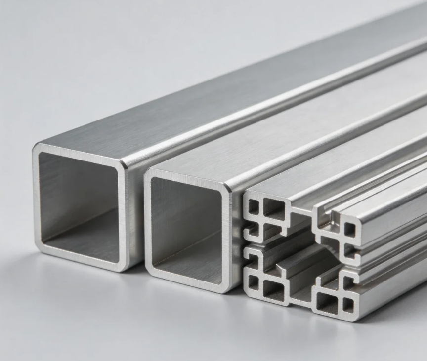
International demand: Dual drive by new energy and infrastructure

The advantages of using aluminium profiles to manufacture robot arms
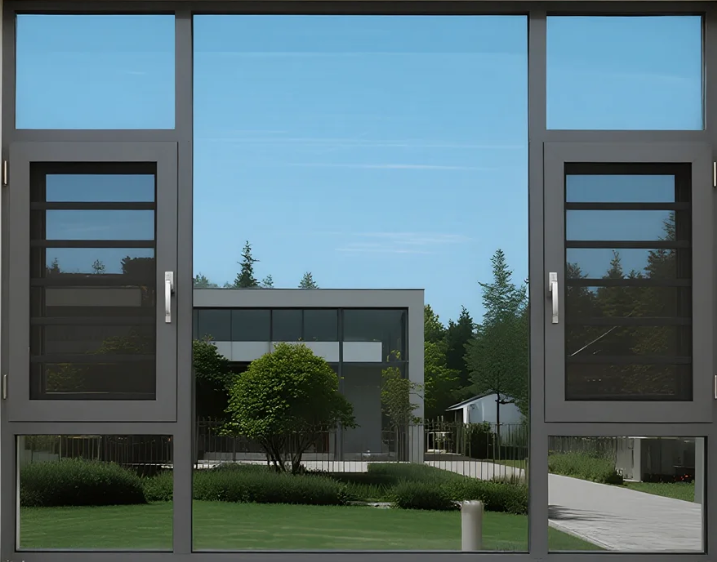
The advantages of using aluminum profiles for door and window frames
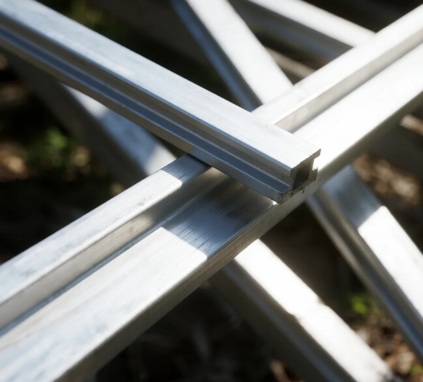
The impact of the conflict between the United States and Iran on the price of aluminum
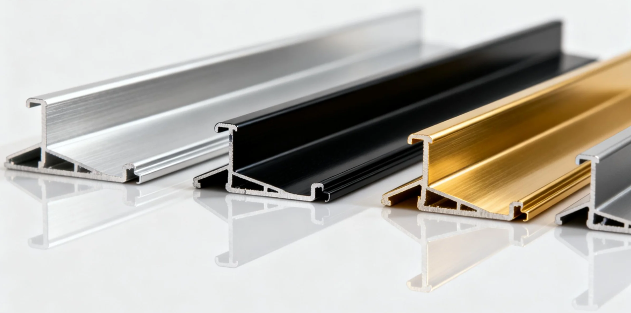
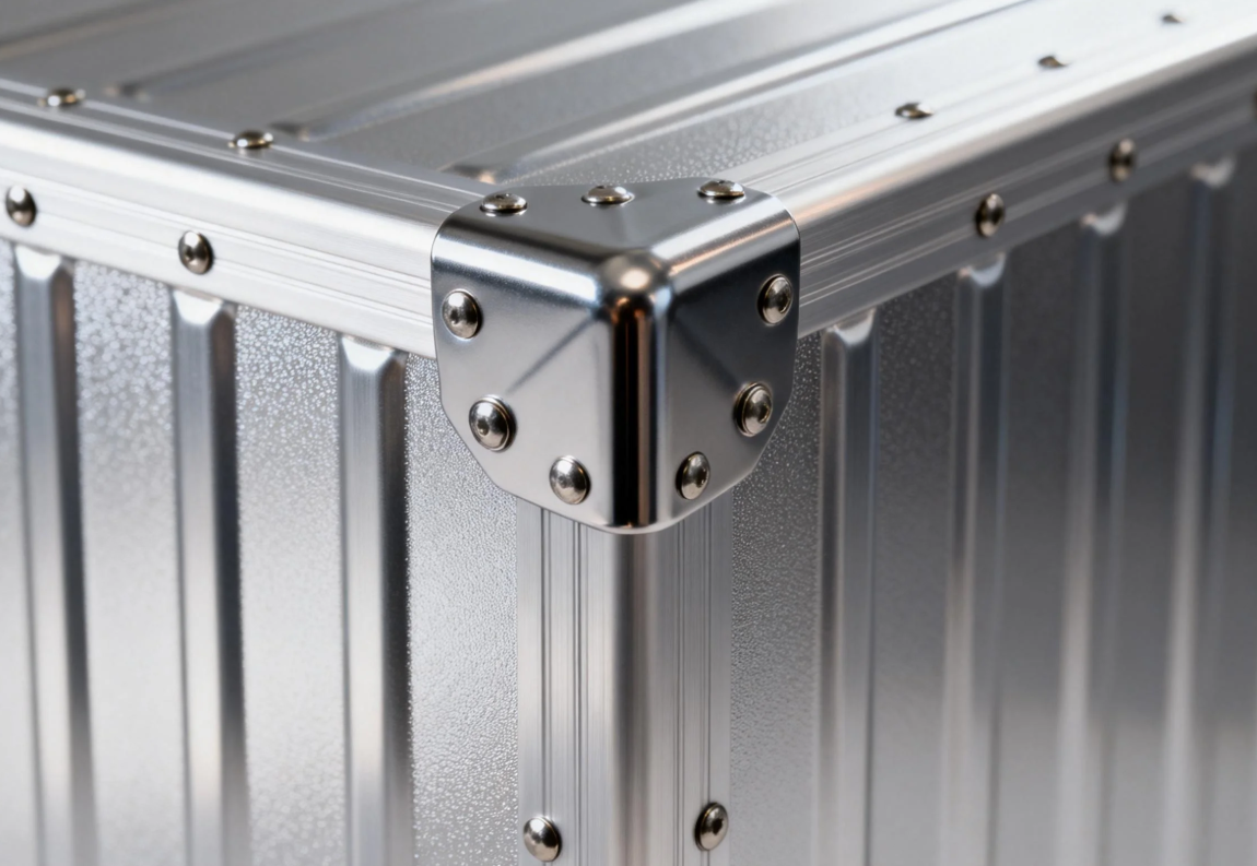
The advantages of using aluminium alloy for the main structure of high-speed train carriages



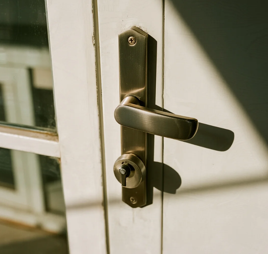
Methods for distinguishing Indoor and Outdoor Aluminium Doors
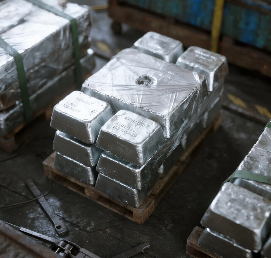
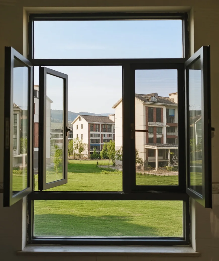
Maintenance methods and tips for aluminium doors and windows
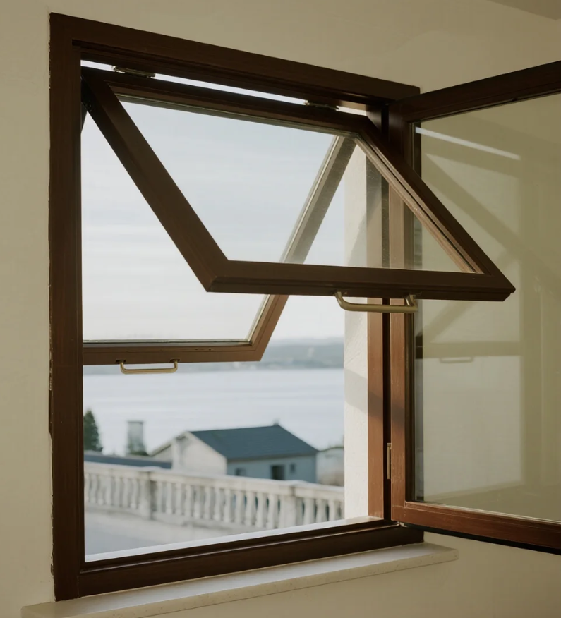
Characteristic of outward-opening and hung aluminium windows


Xinhe Aluminium Research: 7.14-7.18 Analysis of Aluminium Prices
Seven Benefits Of Using Aluminium Profiles In Curtain Wall Systems
The Application of Aluminium Profiles in New Energy Vehicles

The Composition and Application of Series 6 Aluminium Alloys
Top 5 Benefits of Using LED Aluminium Profiles in Modern Lighting
A Complete Guide to Aluminium Frame Profiles for Modern Structures
Exploring the Strength and Versatility of Aluminium Extrusion Profiles
How to Choose the Right Aluminium Profile Supplier for Your Project

COMPANY