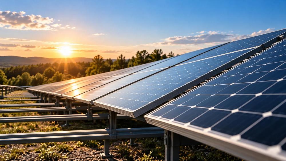
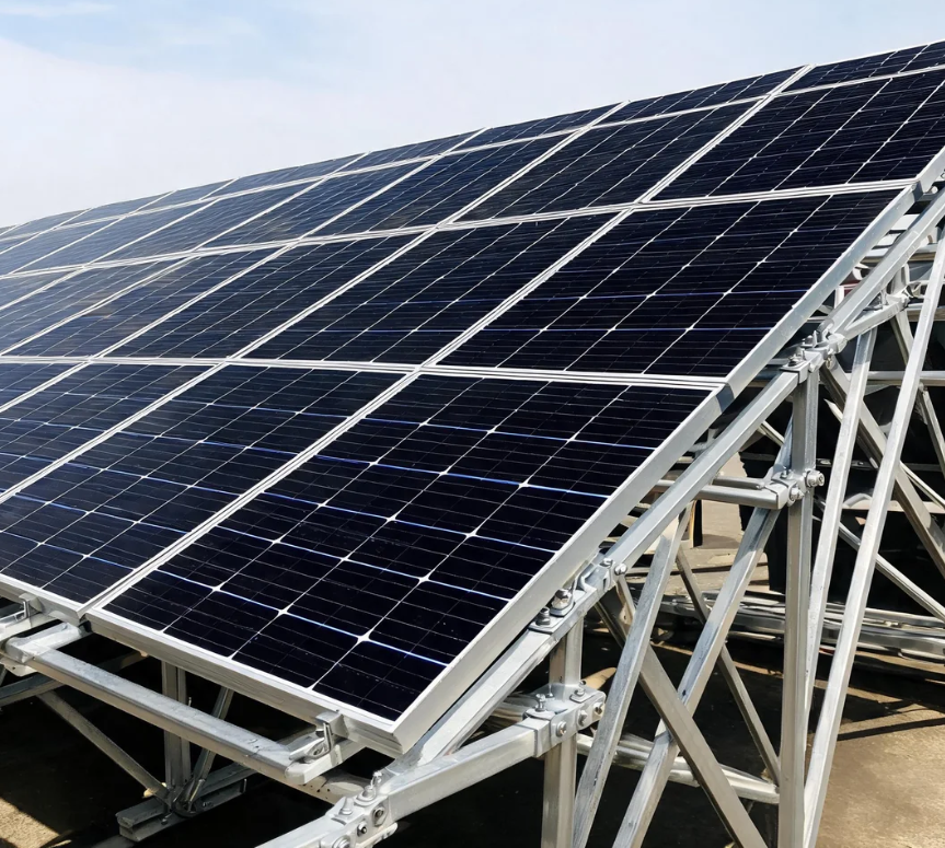
Photovoltaic projects demand structural balance, where mounting frameworks must withstand severe winds, heavy snow loads, and corrosive outdoor air for decades. Selecting high-grade aluminium extrusion profiles for solar panels supports structural reliability because aluminium delivers roughly one-third the density of structural steel, which helps reduce member weight, though the finished profile must still be sized and verified for the actual loads, geometry, and connections of each project. This guide examines mechanical properties, cross-sectional geometries, protective coatings, and precision manufacturing tolerances to help engineers and procurement teams design dependable, cost-efficient solar racking structures.
Solar racking frameworks act as rigid skeletons that secure fragile crystalline silicon modules against relentless environmental forces. When a solar array rests in an open field or across an industrial roof, wind uplift creates alternating dynamic pressures across module surfaces. Without adequate profile stiffness, cyclic stress can contribute to micro-cracking across photovoltaic cells, reducing plant energy generation over time.
Aerodynamic wind uplift generates suction along the windward edges of solar arrays, pulling module clamps upward with considerable force. Allowable deflection limits for a given rail span depend on the applicable building code, the project’s wind design criteria, module manufacturer requirements, and the racking system’s own engineering, so no single ratio applies across every installation. Exceeding the limits set for a specific project risks fastener pull-out, rail warping, and stress on the photovoltaic laminate glass.
Snow accumulation introduces downward compressive loading, particularly on low-tilt commercial rooftop installations. The governing snow load for a project depends on local ground snow load data, roof slope, exposure, and the relevant structural code, rather than a single universal pressure value. Structural profiles must maintain adequate bending stiffness along their primary vertical axis, sized to the project’s specific snow and wind load combination, to resist bending without requiring excessive metal thickness.
Solar arrays experience daily temperature fluctuations, often shifting from near-freezing winter nights to summer surface temperatures well above typical ambient readings. Because aluminium has a higher coefficient of thermal expansion than steel or concrete, long rail strings expand and contract continuously relative to underlying steel purlins or concrete foundations.
Rigid structural systems that ignore thermal movement can accumulate internal stresses that loosen mechanical bolts or bend module frames over time. Accommodating this movement generally relies on expansion joints and rail splice arrangements specified by the racking system’s manufacturer, together with installation gaps sized for the expected temperature range at the project site. Ordinary mid-clamps, which hold adjacent module edges in place, are not a substitute for these dedicated expansion provisions and should not be assumed to allow rail sliding unless the system manufacturer specifically designs and documents them for that purpose. This distinction helps prevent localized stress concentrations, protecting the mechanical integrity of both the framing and the electrical connections within junction boxes.
Direct contact between dissimilar metals can trigger galvanic corrosion whenever moisture acts as an electrolyte. Solar installations often secure aluminium mounting rails to galvanized steel posts or rely on grade 304 or 316 stainless steel bolts. Because aluminium sits lower on the galvanic series than stainless steel, it can act as the sacrificial material and corrode preferentially if the connection is not properly isolated.
Reducing this localized degradation requires careful electrical isolation across metal-to-metal boundaries throughout the array, while still meeting the system’s required bonding and grounding arrangements for electrical safety:
Selecting the appropriate extrusion alloy affects structural load margins, production die speed, and total raw material expense. Magnesium and silicon represent the primary alloying additions within 6000-series structural alloys, forming magnesium silicide precipitates that strengthen the metallic matrix during controlled thermal aging treatments.
Alloy 6063 remains a common standard for distributed rooftop rails and perimeter solar module frames due to its favorable extrusion flow and uniform surface appearance. It provides a workable balance between moderate structural yield strength and clean surface finishes suitable for high-grade anodizing baths, which is one reason it appears so often in standard rail catalogs rather than in heavy load-bearing members.
Alloy 6060 provides fast extrusion speed and thin-wall capabilities, making it a common choice for cost-sensitive components that experience lower mechanical stress, such as trim pieces and lightly loaded brackets. Alloy 6061, by contrast, incorporates small additions of copper and chromium, increasing yield strength for ground-mount foundations, torque tubes, and high-load crossbeams, where the extra alloying cost is offset by the ability to use smaller or thinner sections for the same load.
General-purpose property figures for these alloys are widely published in aluminium industry references, but they are tied to a specific material standard, product form, and section thickness range, none of which this guide can verify independently for a given supplier’s extrusion. Because stated strength and elongation values depend on those conditions, this article does not reproduce a numeric property table here. Engineers and procurement teams should request certified mill test or material test reports for the specific profile, alloy, and temper from the chosen manufacturer before finalizing a structural design, rather than relying on generic published figures.
The temper designation defines how the profile is processed after extrusion to develop its final mechanical properties, with the two most common tempers for solar racking profiles being T5 and T6.
A T5 temper involves cooling the hot profile from the extrusion process, commonly through fan-assisted air cooling on the run-out table, followed by artificial aging in a furnace at roughly 175 to 205 degrees Celsius to develop the final properties.
A T6 temper means the profile is solution heat treated, quenched, and then artificially aged. Solution heat treatment is often achieved through water quenching, though the specific quenching method depends on the alloy, section, and the extruder’s process controls, so water quenching at the die exit should not be treated as the only route. Subsequent aging precipitates fine magnesium silicide throughout the aluminium crystals, which generally raises yield strength compared with T5. Temper affects strength rather than the material’s elastic modulus, so T6 should be described as offering higher strength rather than higher rigidity; section geometry remains the primary factor governing stiffness.
Extrusion Press Exit
       │
       ├─► Cooling from Hot Working ──► Artificial Aging ────► T5 Temper (Moderate Strength, Low Distortion)
       │
       └─► Solution Heat Treatment ─► Quench ─► Artificial Aging ────► T6 Temper (Higher Strength)
Choosing between T5 and T6 tempers influences project budgets and strength margins. While T5 can provide sufficient strength for lightweight short-span solar panels, T6 is generally considered for high-wind geographic zones and long-span utility racking profiles, subject to the project’s own structural design verification.
Structural engineering for solar racking generally prioritizes placing available metal mass away from the neutral bending axis of a section, which increases bending stiffness without necessarily adding weight. Simply increasing wall thickness across an entire profile wastes material, raises transportation costs, and adds dead load to existing rooftops, so geometry is usually the first lever designers reach for before specifying a heavier section.
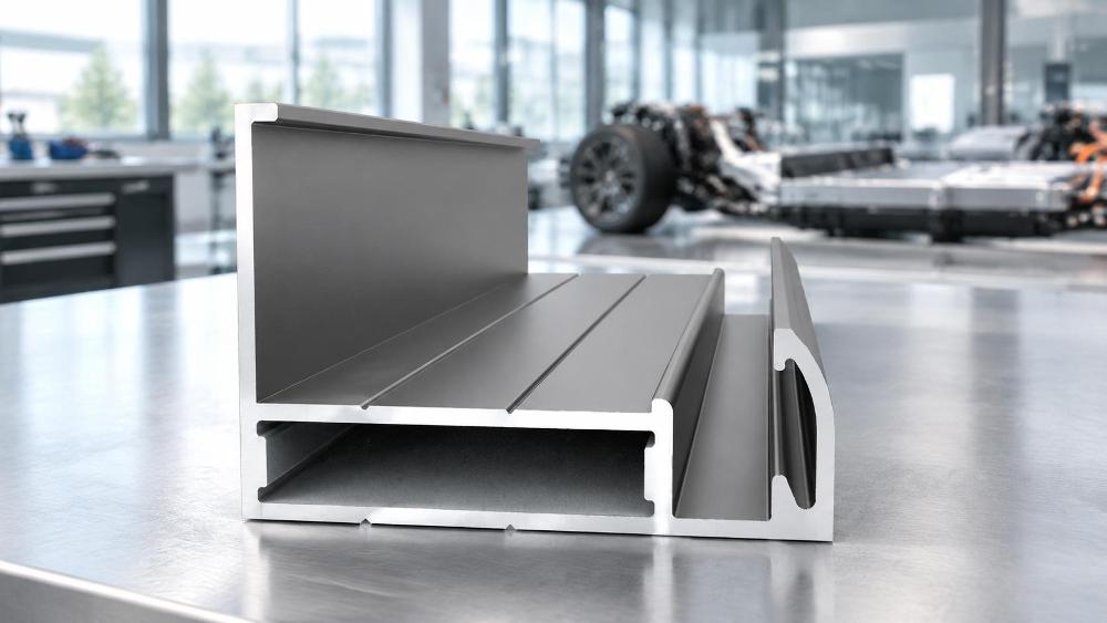
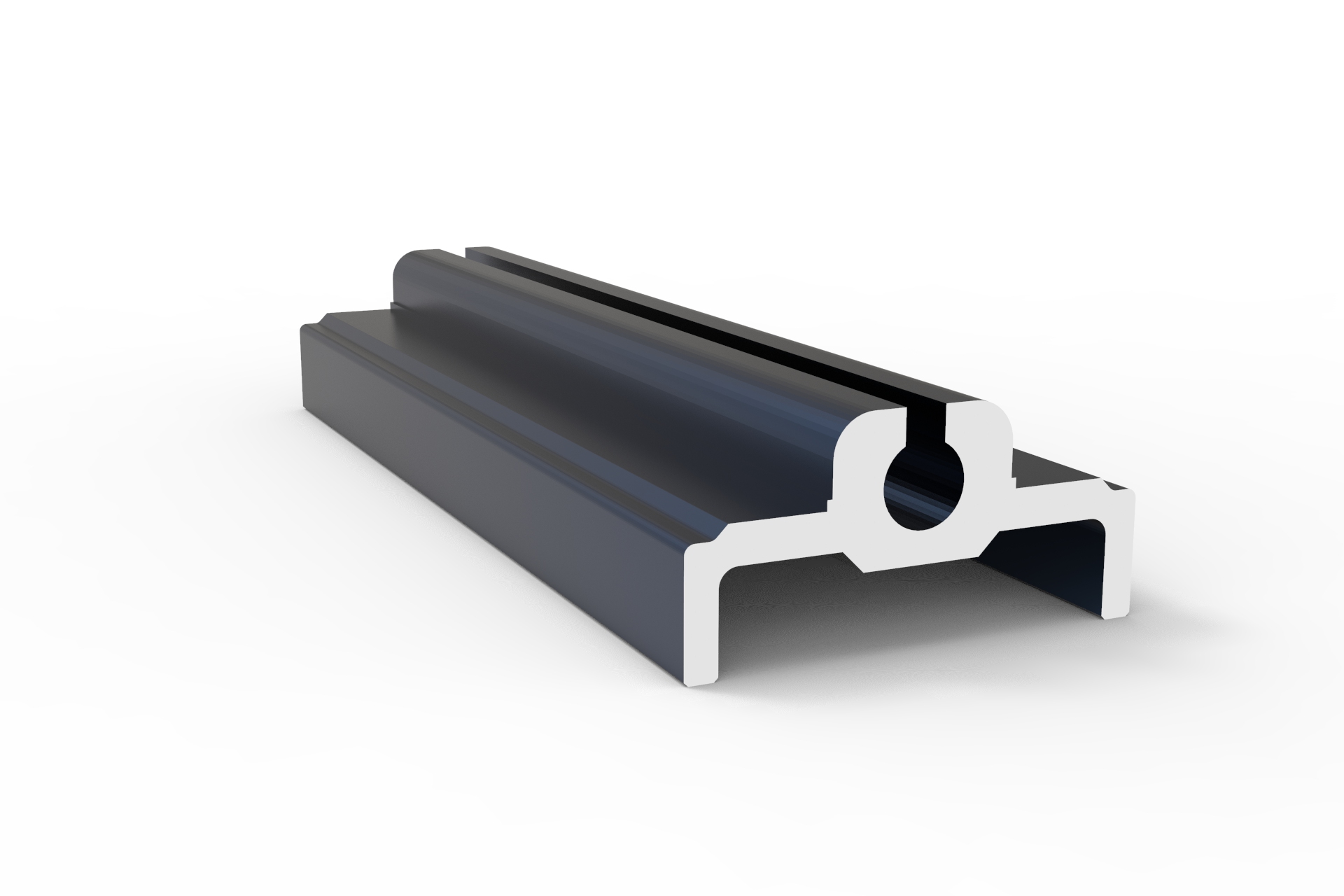
Open C-channels and U-profiles offer straightforward extrusion paths and simple clamping access, but they generally exhibit lower torsional resistance when subjected to uneven wind loading. Under heavy lateral wind gusts, single-web open profiles can twist along their length, creating localized prying forces that may pop module clips out of place.
Multi-chamber hollow box beams address this torsional vulnerability by closing the structural perimeter and adding internal reinforcing webs. Closing the section and adding internal partition walls generally increases the section’s torsional constant, which is the relevant property governing resistance to twisting in a noncircular section, helping it resist dynamic twisting without substantially increasing total profile weight. The actual torsional performance of a given design depends on its specific geometry and should be verified for the section in question. These multi-cavity designs help keep long-span ground-mount tables aligned during seasonal storms.
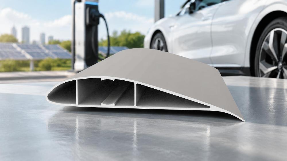
Some purpose-designed solar profiles incorporate functional channels directly into their perimeter, which can reduce the need for on-site drilling and cutting on the specific rail and clamp system they were designed for. Where present, these continuous guide channels are built to accommodate matched hammer-head bolts, sliding hex nuts, or grounding clips supplied as part of the same mounting system, rather than being a universal feature of every solar extrusion.
Pull-out resistance represents a defining metric for internal channel design on profiles that include these features. Structural engineers verify that channel retention lips maintain sufficient thickness and corner radii, appropriate to the specific profile and fastener system, to resist shear tear-out under the project’s peak tensile uplift loads.
Untreated bare aluminium naturally develops an ultra-thin amphoteric oxide film when exposed to air, offering basic atmospheric protection in neutral environments. In industrial corridors, agricultural areas with ammonia emissions, or coastal shorelines loaded with airborne marine salts, this natural film can degrade, leading to pitting corrosion that thins load-bearing walls over time.
Anodizing electrochemically converts the aluminium surface into a porous anodic aluminium oxide layer integral to the substrate. Under thickness-class systems referenced in anodizing standards such as ISO 7599, classes like AA10, AA15, and AA25 denote a minimum average coating thickness of 10, 15, and 25 micrometers respectively, along with separate minimum local thickness requirements. The appropriate class for a given project depends on the specification and the actual exposure conditions rather than a fixed distance from any particular feature such as a coastline:
Maintaining proper hydrothermal sealing after anodizing supports long-term barrier protection. Incomplete sealing leaves microscopic pores open within the oxide layer, inviting moisture ingress that can cloud and degrade the protective finish.
Electrophoretic coating is a process in which charged polymer resin particles are deposited onto the aluminium surface under an applied electric field, producing a uniform organic barrier layer across the profile. On some product lines this electrophoretic layer is applied over an anodized base, forming a dual-layer system intended to combine the barrier properties of the oxide layer with the organic coating; whether a given profile uses this combined approach depends on the manufacturer’s specific process and should be confirmed with the supplier. Where used, the electrophoretic layer is generally intended to provide more even coverage across complex profile channels than standard liquid spray coatings, which can thin out at sharp internal corners.
Fluorocarbon coatings based on polyvinylidene fluoride (PVDF) resins are widely used in architectural and outdoor aluminium finishing for their resistance to ultraviolet radiation and long-term color retention. The stable carbon-fluorine bond is associated with resistance to chalking, blistering, and chemical erosion over long-term outdoor sunlight exposure, supporting the profile’s underlying mechanical capacity, though actual weathering performance depends on the specific resin formulation and coating system applied by the manufacturer.
Transitioning custom solar profiles from engineering concepts to scalable production requires balancing structural requirements against extrusion press capabilities. Extrusion dies face pressure and thermal wear when forcing heated aluminium billets through intricate thin-walled shapes.
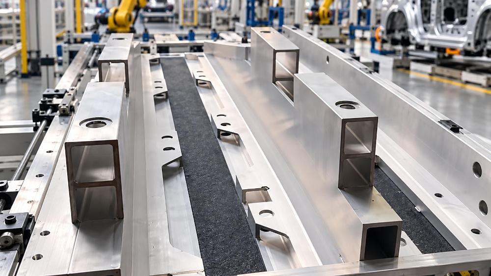
Extrusion dies must balance metal flow rates across varying section thicknesses to prevent profile warpage, wave defects, and uneven cooling rates. Abrupt transitions between thick structural flanges and thin cosmetic ribs can cause stress concentrations within the die tooling, risking premature fatigue failure.
Balancing project deployment schedules requires a thorough understanding of extrusion production lead times, die manufacturing cycles, and shipment logistics. For specialized projects, working with an established manufacturer helps ensure consistent alloy chemistry, controlled tempering cycles, and reliable delivery schedules.
Xinhe Aluminium operates as a dedicated aluminium profile manufacturer with over 25 years of industry experience since its founding in 1998. Integrating research, manufacturing, and distribution, the company maintains an annual production capacity of 200,000 tons and serves clients across more than 50 countries and regions. With a catalog spanning more than 5,000 profile designs across architectural, industrial, and standard categories, custom fabrication services adjust dimensions and surface treatments and draw on available alloy selections to match project specifications, including aluminium extrusion profiles for solar panels and related racking components.
Procurement managers should evaluate the following structural supply criteria when planning large-scale deployments:
There is no single safe minimum wall thickness that applies across all rooftop rail designs. The required thickness depends on the specific profile geometry, the applied wind and snow loads, the fastener and clamp system, and the span between supports, so it must be determined through structural design and verified for the selected profile and connections rather than taken from a generic figure.
Alloy 6061-T6 may be considered when a design calls for higher yield strength than 6063-T6 provides, such as in heavy utility-scale tracker cross-arms or high-load shared purlin assemblies. Its yield strength is meaningfully higher than that of 6063-T6, which can help carry heavier loads, but any resulting change in allowable span, deflection, or foundation design depends on the complete structural analysis, including section geometry, connections, and project-specific loading, rather than on yield strength alone.
Anodic oxide coatings gradually wear through chemical abrasion and atmospheric exposure over time, though the rate varies by environment. Specifying a coating that meets a minimum average thickness class, such as AA15, is a common approach for standard inland environments, while more aggressive marine or industrial exposure often calls for a thicker class such as AA25 under the applicable project specification. The appropriate class should be confirmed against the governing anodizing standard and the site’s actual exposure conditions.
Reducing galvanic corrosion involves electrically separating dissimilar metals at their point of contact. Installers commonly place UV-resistant EPDM rubber pads or nylon isolation washers between the bottom of the aluminium rail and the galvanized steel purlin to interrupt the galvanic current path. Fastener and isolation components should also be compatible with the system’s required bonding and grounding arrangements, since electrical safety requirements for the array must still be met alongside corrosion control.
Custom cross-sections can reduce mechanical installation labor by incorporating integrated bolt-sliding tracks, snap-fit wire raceways, and internal splice alignment channels directly into the extrusion geometry. Field crews can avoid much of the manual drilling, tapping, and loose wire fastening otherwise required, and modules can clamp into position with standard hex drivers, which can help speed up project commissioning. The actual labor savings will vary by project and installation method.
Designing robust solar mounting structures demands a balanced approach that pairs structural mechanics with informed metallurgical and surface treatment choices, verified against the applicable codes and site conditions for each project. Weighing wind uplift and snow accumulation against section stiffness and torsional performance allows engineering teams to manage metal weight without compromising structural safety. Incorporating functional mounting channels and effective galvanic isolation helps safeguard structural integrity across changing outdoor climates.
Selecting well-engineered aluminium extrusion profiles for solar panels, sized and verified for the project’s actual loads, helps keep renewable energy infrastructure safe, durable, and cost-effective over its operating lifetime. By aligning alloy selection, protective anodizing standards, and sound manufacturing design practices with the specific requirements of each installation, solar developers and engineering contractors can better protect their clean energy investments for years to come.
The Definitive Guide to Aluminium Extrusion Profiles: Engineering Principles, Modular Systems, and P
Could smart Casement windows become a practical alternative to standard models?
Is it practical to develop a private-label Sliding window for my brand?
What spare parts should I stock for Floding door after-sales support?
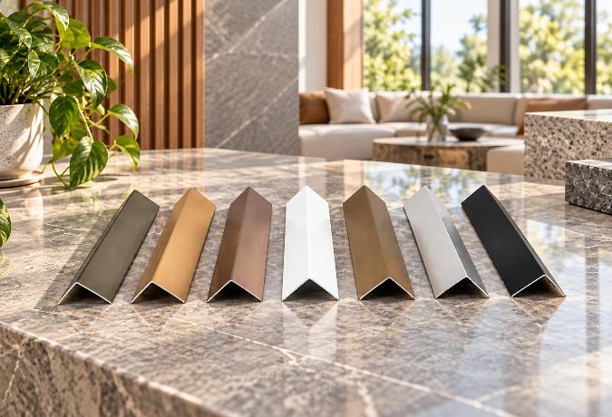
Architectural and Industrial Aluminium Angle Profile Guide: Structural Sizing, Alloy Selection, and
How can I prevent my Casement window color formula from being reused?
What coating compliance evidence should I request for Decorative profile?
What information helps a factory understand my Sliding door customization needs?
Are new Shutter materials improving durability while reducing total project cost?
What extra charges should I ask about when buying Casement doors?
What files do I need to provide for a custom Decorative profile?
Should I hold the final Shutter payment until an independent inspection passes?
Are Decorative profile tooling fees normally refundable after reaching volume targets?
What defective-rate threshold should trigger compensation for Casement windows?
How can I tell whether an Architecture profile seller owns a real factory?
Can Shutter slat shapes be customized without creating long tooling delays?
Can a remote audit reliably confirm Sliding window quality controls?
How do I confirm an Architecture profile meets the required wall loads?
Can missing Casement window test reports delay customs clearance or installation?
How should I send CAD details for a custom Casement door design?
Choosing Industrial Aluminium Profiles for Laser Cutting Machines: A Technical Guide
How LED Aluminium Profile Heatsinks Manage Thermal Challenges in High-Performance Lighting
Architectural Aluminium Profiles: Choosing the Right Angle Design for Framing and Trim
Choosing the Right Aluminium Door Profiles for Narrow-Frame Sliding Systems
Aluminium Window Profiles: Engineering Durable Facades for Modern Buildings
Aluminium Wardrobe Profiles: A Practical Guide to Frames, Tracks, and Finishes
Choosing the Right Aluminium Linear Rail Profile for Motion Systems
Anodized Aluminium Profiles: Material Selection and Practical Applications in Modern Design
Aluminium Decorative Profiles: Design, Installation, and Interior Applications
Aluminium Profiles for Automation: A Practical Guide to Modular Frame Design
Aluminium Extrusion for Furniture: Structural Logic Behind Lightweight Precision
Aluminium Thermal Break Profiles: Design Principles and Practical Applications
How do suppliers normally handle Sliding door installation problems overseas?
Choosing the Right Aluminium Balustrade Profiles for Your Project
Aluminium Louver Profiles: Light Control and Ventilation in Modern Architecture
Aluminium Curtain Wall Profiles: Structural Design and Performance in Modern Architecture
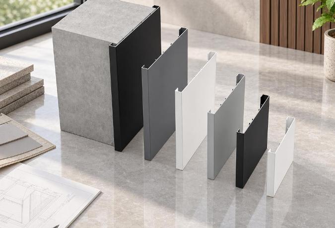
Aluminium Trim Profiles: Bridging Aesthetics and Performance in Modern Interior Design
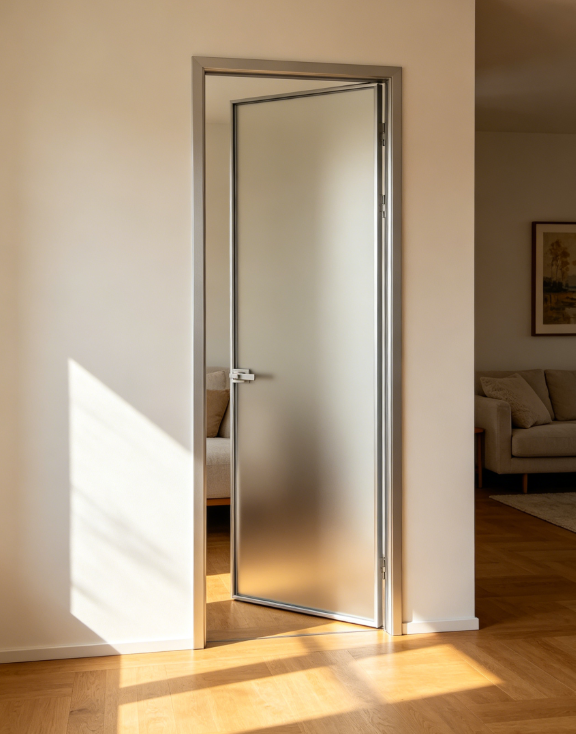
How do I verify Casement window production capacity before signing a contract?
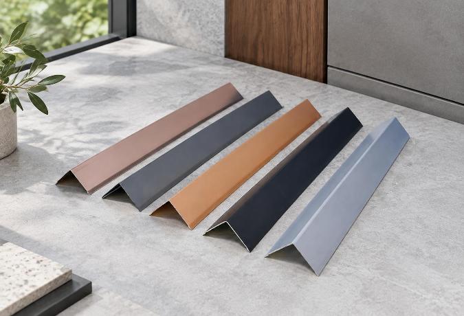
Powder Coated Aluminium Profiles: Durability and Design in Modern Applications
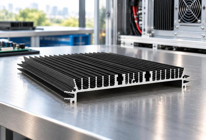
How Aluminium Heatsink Profiles Keep Electronics From Cooking Themselves
How do FOB and CIF change my risks when importing Sliding doors?
What support should I receive if Architecture profile dimensions are wrong?
Inside an Aluminium Profile Factory: How Angle Profiles Are Made and Chosen
What is a realistic MOQ for a first Sliding window trial order?
Which factory records should I review before buying Industrial profile?
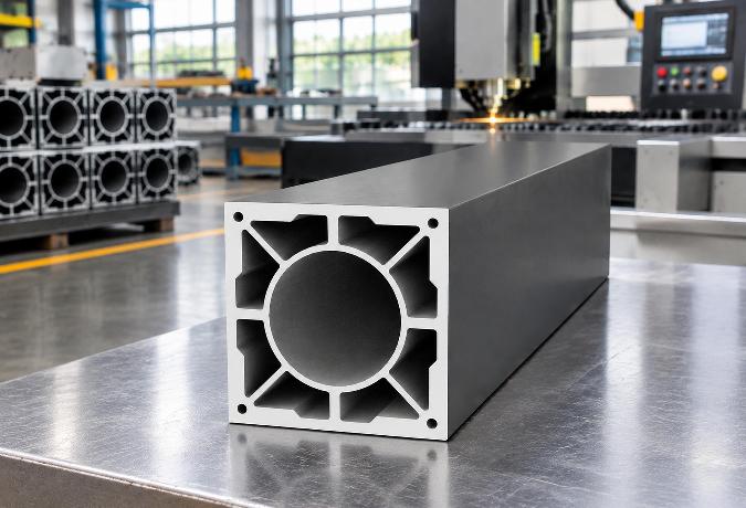
Aluminium Extrusion for Machinery: Choosing the Right Profile for Industrial Equipment
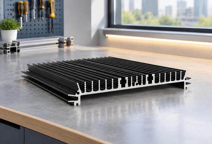
Aluminium Extrusion for LED Lighting: Choosing the Right Heatsink Profile
Can a Floding door supplier protect my private design from competitors?
Which Industrial profile tolerances affect assembly accuracy and finished quality?
Can trade credit insurance cover my Architecture profile purchase risk?
Custom Aluminium Extrusion Profiles: Engineering Precision into Industrial Motion Systems
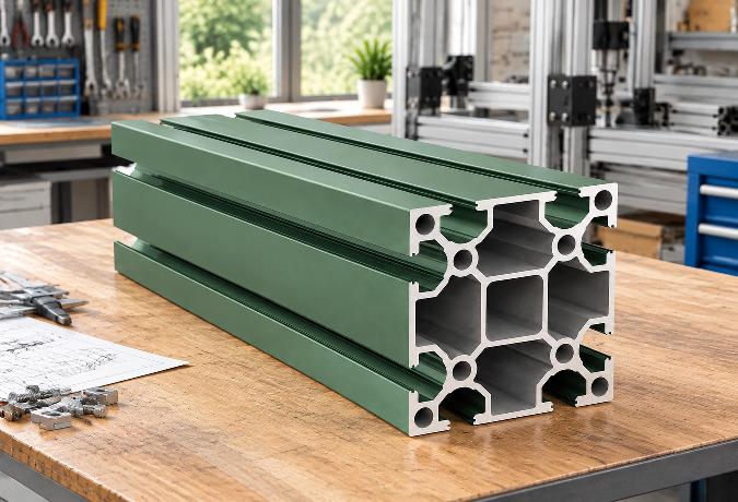
T-Slot Aluminium Extrusion: Structural Framework Design Without Welding
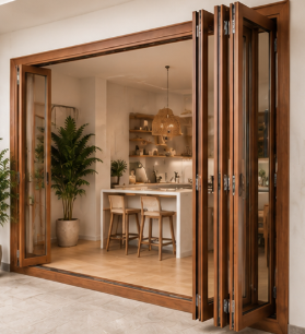
Which recycled-content records are credible for Sliding window procurement?
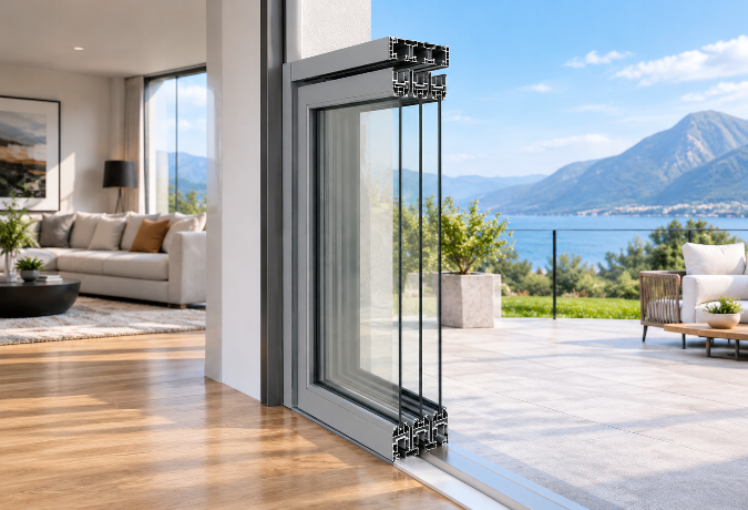
Aluminium Sliding Door Profiles: A Practical Guide to Frame Design and Performance
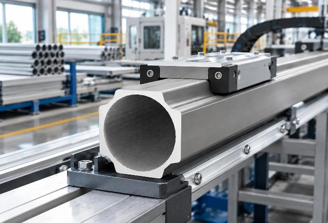
How Aluminium Extrusion Manufacturers in China Support Linear Motion Systems
What contract clauses protect my money if Casement door quality is unacceptable?
How do I confirm Sliding door testing equipment is calibrated and current?
Should I visit an Architecture profile plant before placing a large order?
Which compliance tests should a Floding door pass before international shipment?
How do I compare Decorative profile color samples under different lighting?
What payment and price terms make sense for a small Casement window order?
What lead time should I allow for a seasonal Floding door order?
How can I compare Floding door alternatives when supply costs suddenly rise?
Which new Sliding door technologies can lower maintenance costs over time?
How are recycled materials changing the future cost of Floding doors?
How long should a custom Casement door sample normally take to prepare?
What gap between a Sliding window sample and bulk order is acceptable?
Which Decorative profile finishes are becoming more sustainable and cost-effective?
What logistics fees should be listed separately in a Sliding window quote?
How might volatile aluminum prices affect future Sliding window sourcing?
Which audit questions reveal labor risks at a Casement door factory?
Can Decorative profile suppliers provide fast remote guidance for finish defects?
What should a Shutter sample include so I can assess production quality?
Do Sliding door materials need traceability records for customs clearance?
What environmental declarations are useful when importing Architecture profile?
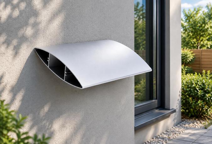
Why Blade Geometry Determines Whether Aluminium Louvers Actually Work
Engineering an Aluminium Angle Profile: Structural Mechanics and Application Realities
What usually drives Architecture profile costs more, alloy or surface treatment?
Why the One-Piece Molding on Aluminium Trim Profiles Matters More Than the Finish
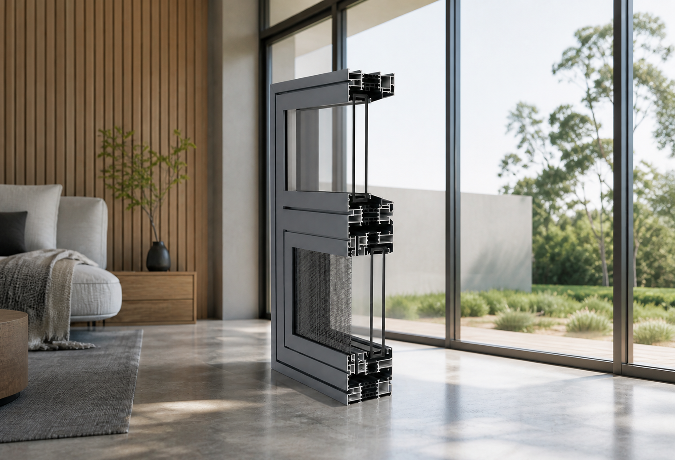
Why the Thermal Break Cavity Matters More Than Frame Thickness in Aluminium Framed Windows and Doors
The T-Slot Groove Geometry That Makes Aluminium Framing Weld-Free
Why the One-Piece Molding on Aluminium Trim Profiles Matters More Than the Finish
Structural Dynamics of Industrial Aluminium Profiles in Laser Cutting Gantries
The Engineering Mechanics Behind High-Performance Aluminium Shutters
What factory documents should I request for a Floding door supplier review?
Which delivery term gives me better control over Decorative profile freight costs?
What low-carbon Awing window materials are gaining wider market acceptance?
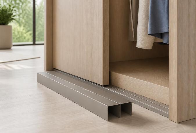
Why Sliding Door Track Geometry Determines Wardrobe Longevity
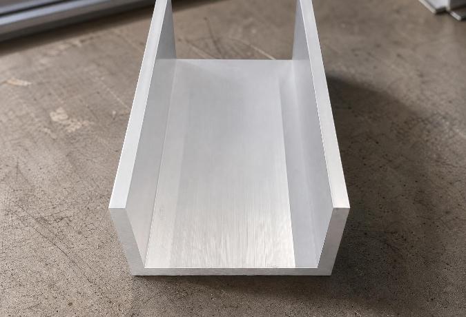
Engineering Mechanics and Surface Dynamics of Aluminium Channel Profiles
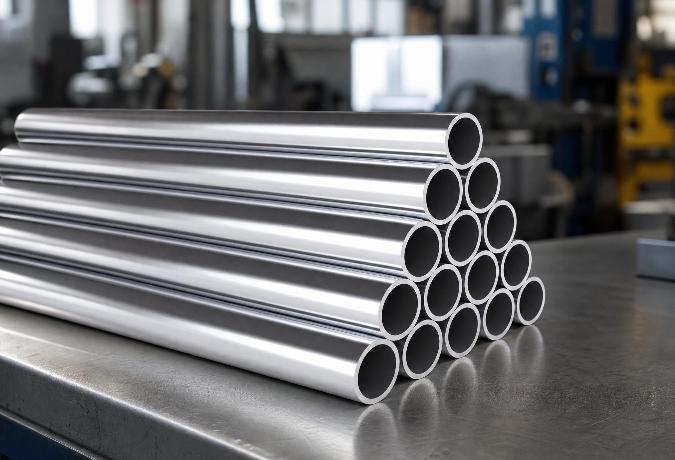
Understanding Aluminium Round Tube Specifications for Structural Engineering
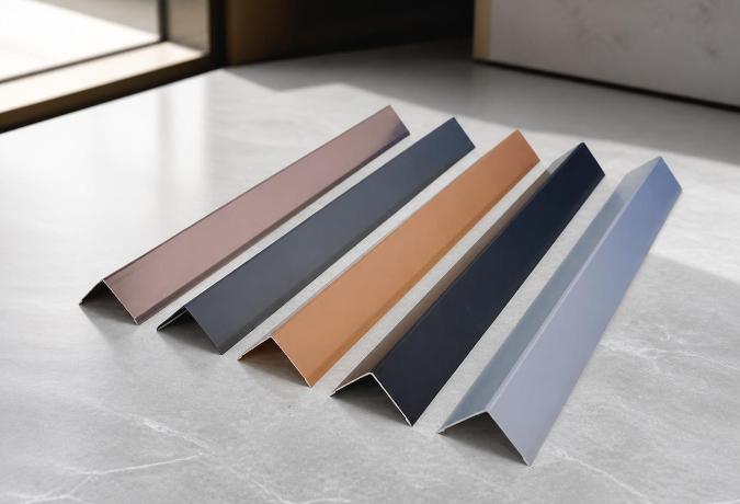
Why the 90-Degree Angle in Standard Aluminium Profiles Determines Structural Reliability
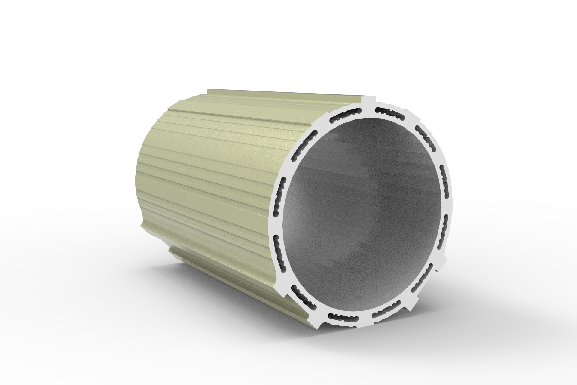
How can I ensure a Floding door sample matches the planned mass production?
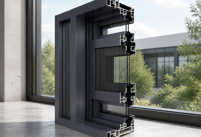
Why Mullion Thickness Determines How Much Glass an Aluminium Curtain Wall Can Actually Hold
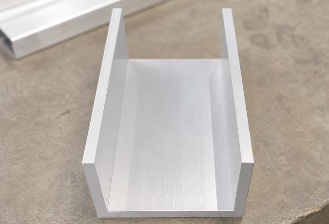
Engineering Dimensional Stability in Aluminium Extrusions for Channel Profiles
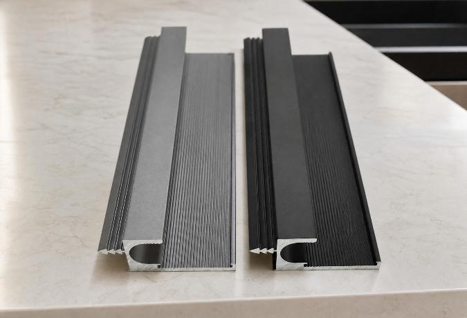
Engineering the Structural Framework: The Mechanics of Aluminium Profiles for Kitchen Cabinets
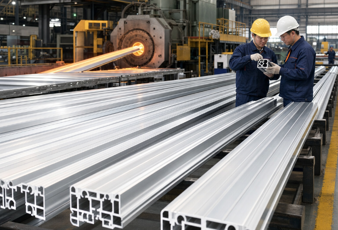
Choosing an Aluminium Profile Supplier: What Actually Separates the Reliable Ones from the Rest
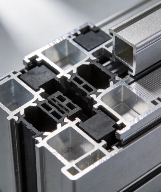
Can Awing window orders ship in batches to avoid project delays?
What response time should I expect for Awing window warranty claims?
Navigating the Supply Chain: Evaluating an Aluminium Profile Manufacturer for B2B Procurement
Engineering Structural Integrity Through Precision L-Shaped Aluminium Profiles
Thermal Dynamics in High-Power Electronics: Engineering Aluminium Heatsink Profiles
Why the T-Slot Design Determines the Real Strength of Structural Aluminium Extrusions
How long should replacement Sliding window parts remain available after purchase?
Should I expect volume discounts when reordering the same Sliding window model?
The Multi-Strip Sealing Structure Inside Aluminium Windows and Doors
Engineering Lightweight Rail Structures Through Extruded Aluminium Profiles
Why the Frame Width on an Aluminium Sliding Door Determines Your Room’s Light
The Engineering Behind Decorative Aluminium Profiles: Alloys, Surface Treatments, and Edge Protectio
What alternative materials could make Casement doors more resilient and recyclable?
How can I compare Awing window quotes without missing hidden packing costs?
Decoding Structural Tolerances in Aluminium Extrusion Profiles for Channel Applications
Engineering an Aluminium Square Tube for Modern Structural Integrity
Engineering Tolerances and Alloy Mechanics in Extruded Aluminium Construction Profiles
The Engineering Mechanics Behind Aluminium Angle Profiles in Modern Construction
Can an Industrial profile be modified for my assembly without weakening it?
What warning signs suggest a Sliding door seller may disappear after payment?
What energy-efficient alternatives to Casement doors are worth comparing now?
Can a Casement window handle temperature changes without seal failure?
Who pays for unloading and destination handling under Casement door CIF terms?
Custom Aluminium Extrusion Profiles: The Engineering Mechanics of T-Slot Frameworks
Material Transitions and Geometric Stability in Decorative Aluminium Profiles
Can I negotiate a lower Sliding door MOQ for a showroom launch?
Key Advantages of Using Structural Aluminium Extrusion Profiles in Construction
What evidence shows an Awing window factory manages coating waste properly?
How can I protect my deposit when ordering custom Decorative profile?
How do I spot unusually low Industrial profile prices before committing funds?
How can I check that a Shutter supplier is not using unapproved subcontractors?
What contract terms protect my Casement door drawings and branding?
How can I compare Casement door insulation ratings before placing an order?
Sourcing Industrial Aluminium Profiles: What to Look For in a Supplier
How do I keep ownership of a custom Architecture profile extrusion die?
The Energy Efficiency Benefits of an Aluminium Frame Sliding Glass Window
How do I check Industrial profile alloy grades against the shipping documents?
What Casement window warranty period is reasonable for an overseas buyer?
How are defective Sliding window units usually replaced internationally?
How can I reduce breakage risks when shipping Casement windows overseas?
The Structural Mechanics Behind Decorative Aluminium Profiles
How Do Engineers Select Industrial Aluminium Profiles for High-Load Frameworks?
What payment structure reduces my risk on a first Industrial profile order?
Should I approve a Casement window sample before checking its hardware strength?
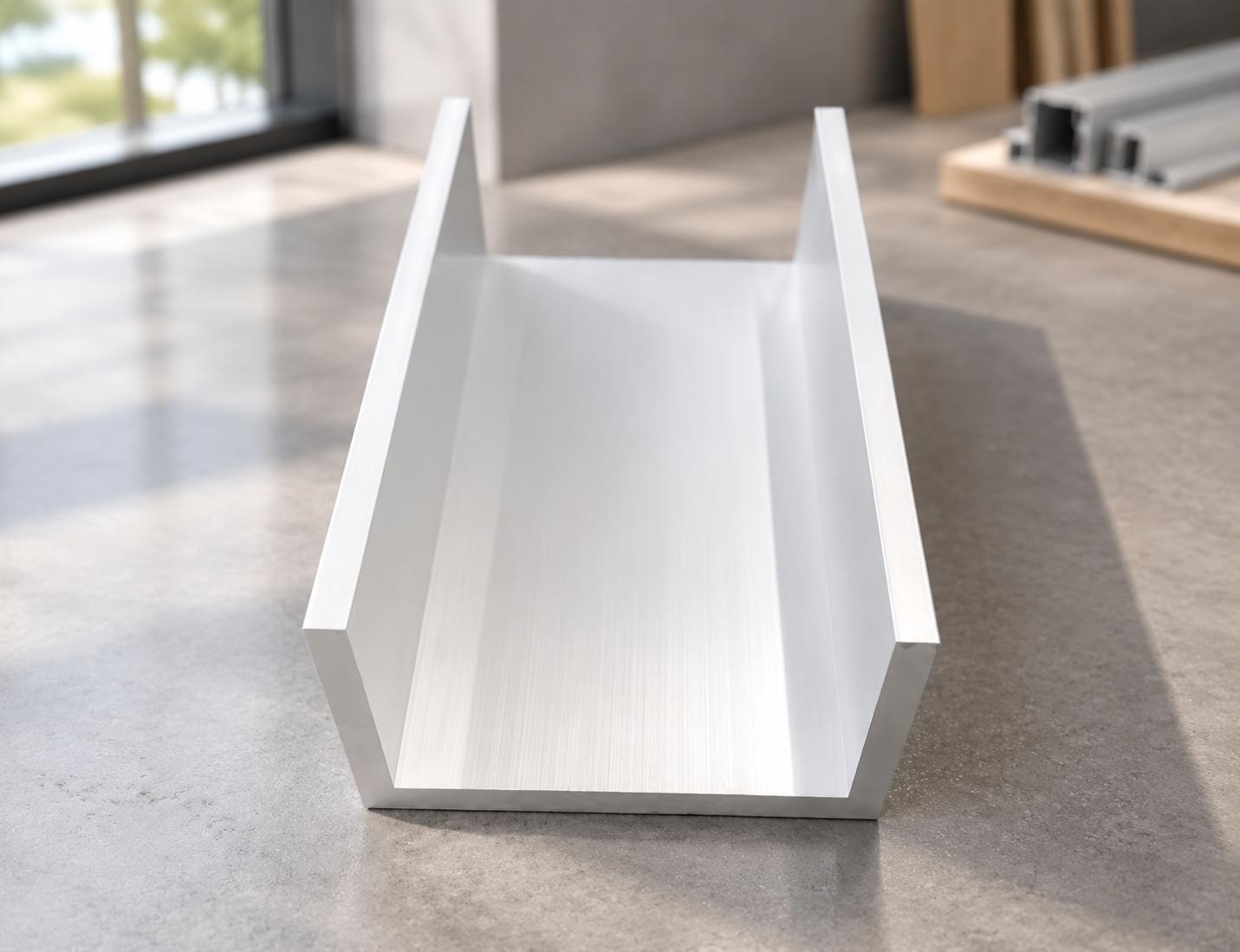
Structural Mechanics of Channel Extrusions in Architectural Aluminium Profiles
Engineering Mechanics of Aluminium Extrusion Profiles in Channel Systems
What functional tests should I perform on a Sliding door prototype?
What payment terms are fair when Decorative profile colors remain unconfirmed?
Is a letter of credit practical for a large Casement window shipment?
How should Industrial profile bundles be packed to prevent transit damage?
Which safety documents should I request for Awing window imports?
What shipping delays commonly affect Architecture profile orders during peak season?
How to Specify Extruded Aluminium Profiles: Costs, Alloys, and Tolerances
Is a Floding door suitable for a wide opening exposed to strong winds?
Structural Integrity in Modular Design: Engineering T-Slot Aluminium Extrusion Profiles
Resolving Corner Stress: The Engineering Mechanics Behind Aluminium Profiles in Architectural Framin
How do Floding door prices change with glass, hardware, and finish choices?
How can I prove Shutter defects remotely without returning every unit?
How can I shorten Awing window sampling without losing critical tests?
Does ordering mixed Shutter sizes usually change the unit price or MOQ?
How should Industrial profile warranty responsibility be shared after assembly?
How should I plan Shutter inventory when ocean freight schedules change?
How do escrow arrangements reduce risk for a new Floding door supplier?
What frame materials make a Sliding window last in harsh coastal weather?
How can I verify that a Shutter certificate matches the actual product?
Can automated Shutters replace manual systems without raising lifecycle costs?
How do I choose the right Casement window size for a windy building?
What should an ethical audit cover at a Decorative profile factory?
How should I document Industrial profile defects before disputing the final payment?
Are lightweight Industrial profile alloys reliable enough for demanding machinery?
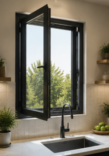
Are thermal-break casement windows becoming a better long-term choice than standard frames?
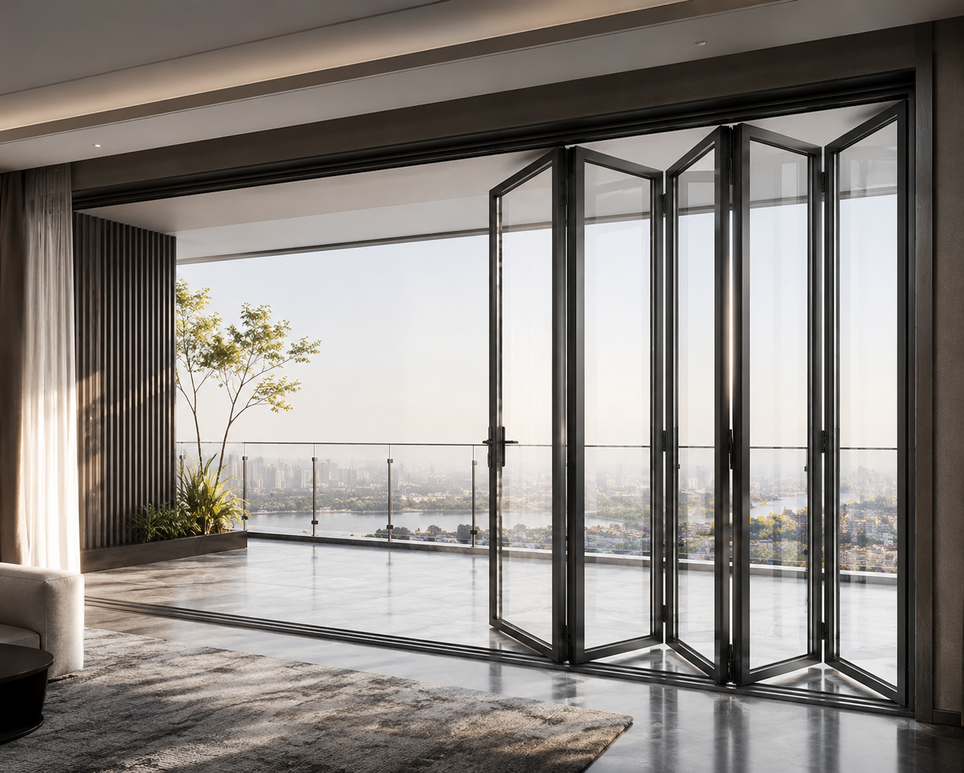
What is a realistic MOQ for custom sliding windows without pushing up unit cost?
What casement window specs should I compare for windy and rainy project sites?
Are there better material options for sliding windows if aluminum prices rise?
How do I ensure aluminum casement windows can handle extreme coastal winds?
What is the typical minimum order quantity for commercial sliding windows?
Are there energy-saving alternatives to sliding windows that reduce material and maintenance costs?
Are energy-efficient Awing windows a practical alternative for reducing long-term building costs?
What alternatives to traditional sliding doors can lower costs without sacrificing durability?
What alternatives to industrial profiles can reduce material costs without hurting strength?
Extruded Aluminium Profiles: Flexible Manufacturing for Diverse Customer Needs
Why Aluminium Curtain Walls Are Popular in Modern Architecture
How do I choose a decorative profile that stays stable in humid or harsh environments?
How do I choose an architecture profile that stays stable in harsh outdoor conditions?
How can I compare Awing window specs to avoid poor performance in harsh weather?
How can I compare Sliding door sizes and hardware ratings for harsh commercial environments?
How do I choose the right shutter specifications for harsh climates without overpaying?
What eco-friendly alternatives to folding doors can cut costs without hurting durability?
How do I choose the right shutter specifications for harsh weather without overpaying?
What eco-friendly casement door materials can lower costs without hurting durability?
What newer materials can replace industrial profiles without raising costs or supply risks?
How do I choose a decorative profile that stays stable in humid, high-traffic spaces?
What sustainable material alternatives can replace aluminum architecture profiles?
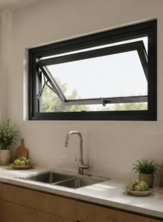
What should I check in Awing window specs to ensure reliable performance in harsh weather?
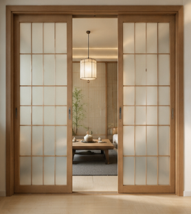
How can I compare Sliding door sizes and thermal ratings for harsh climates before buying?
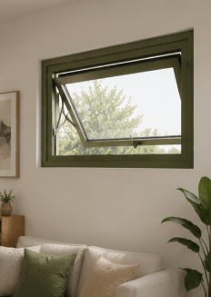
What newer materials can replace aluminum in awning windows without raising our costs?
How do I choose the right Sliding door specs for smooth operation in harsh environments?
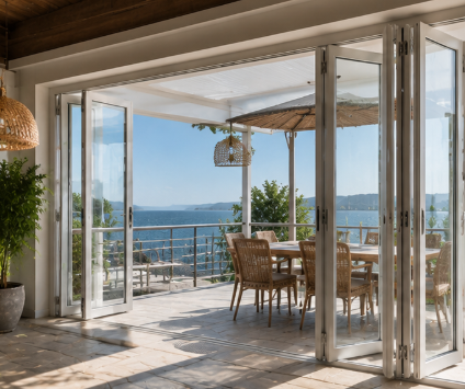
How do I choose a folding door that stays stable in harsh weather and heavy daily use?
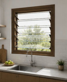
How can I choose the right shutter specifications for harsh weather and long-term use?
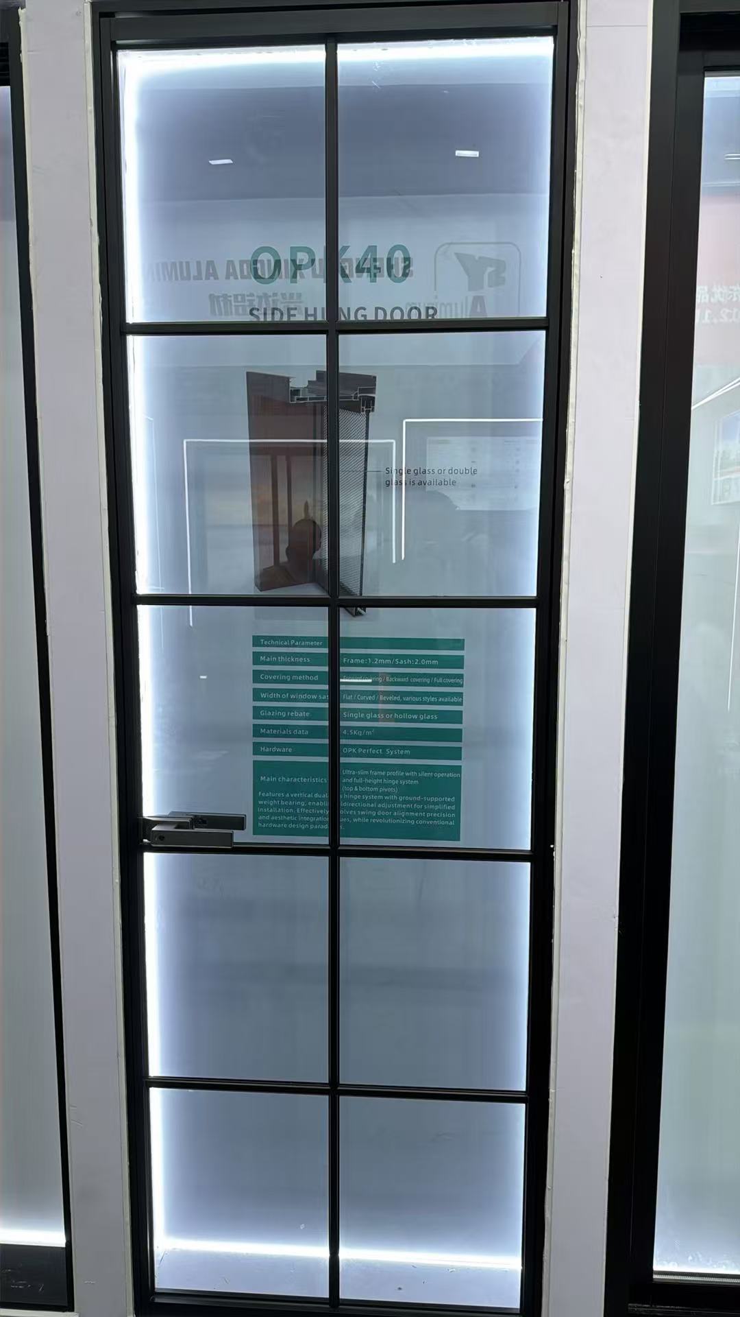
How do I compare casement door U-values, hardware, and weather sealing before buying?
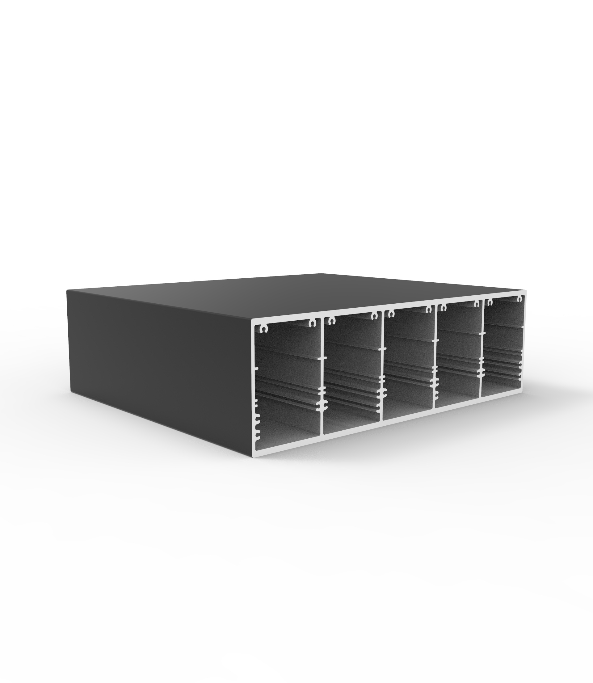
How do I choose the right industrial profile size for strength and load needs?
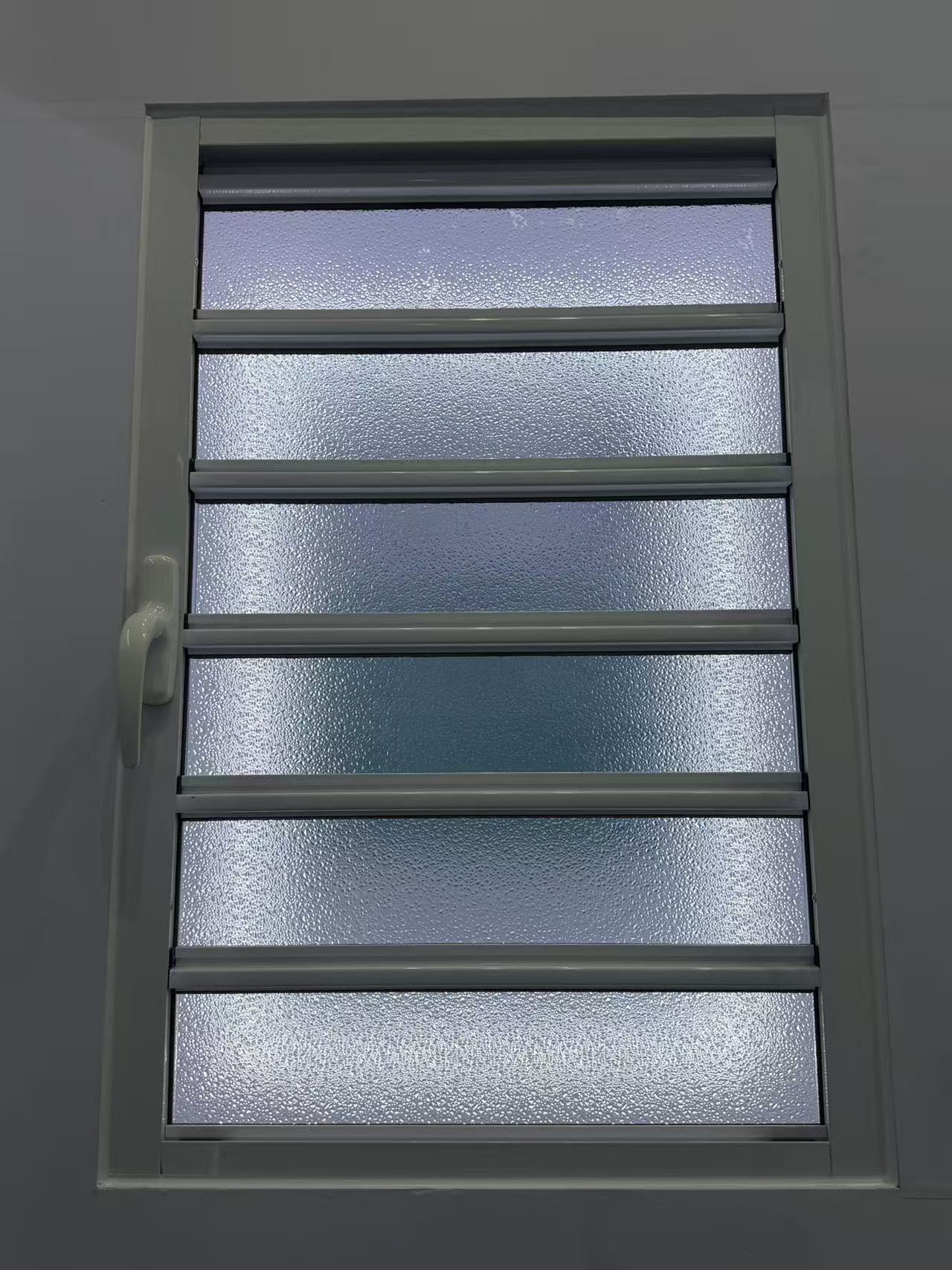
How do I choose the right shutter specifications for harsh weather and long-term commercial use?
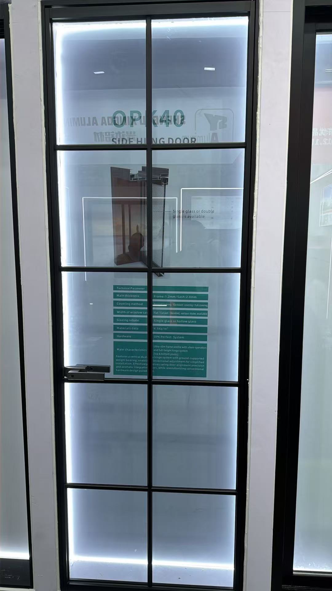
How do I choose the right Casement door size and hardware for harsh weather?
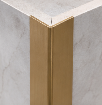
What greener alternatives to decorative profile can cut costs without hurting durability?
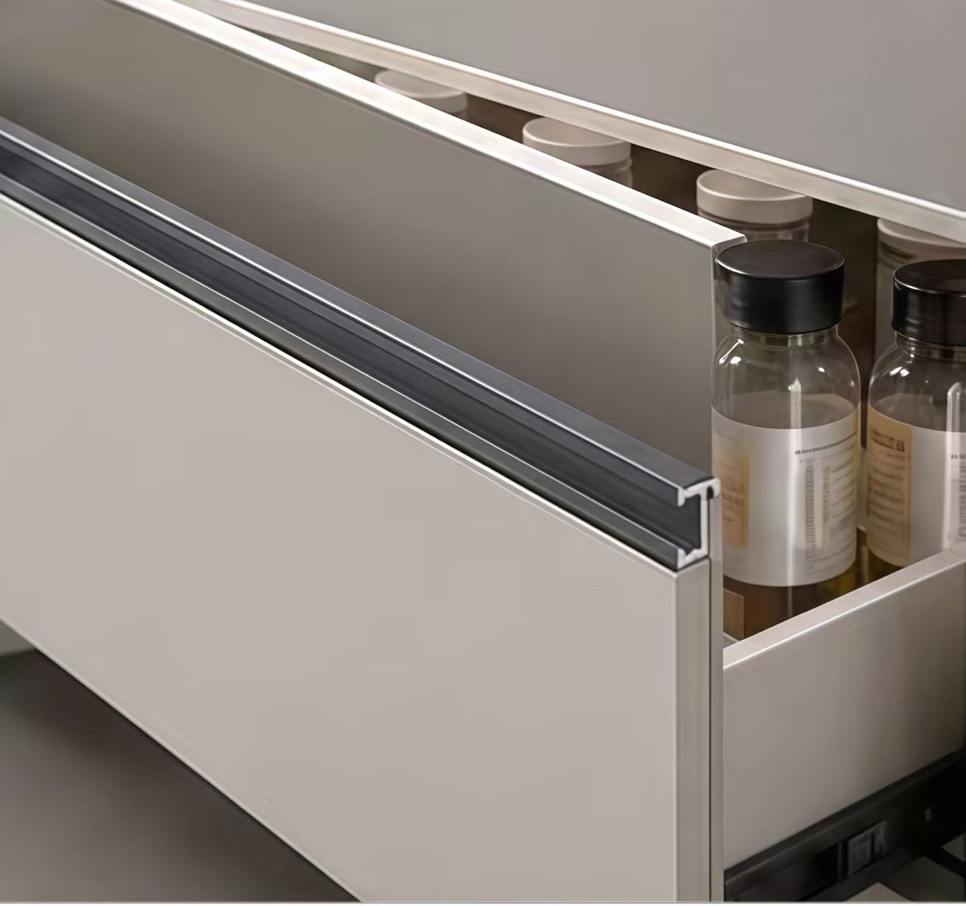
What lower-cost, eco-friendly materials can replace decorative profiles?
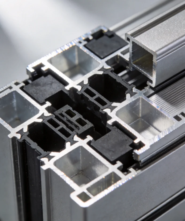
What lower-carbon alternatives to aluminum architecture profiles are practical for our project?
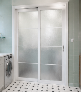
How can I compare sliding door systems for insulation, security, and long-term use?
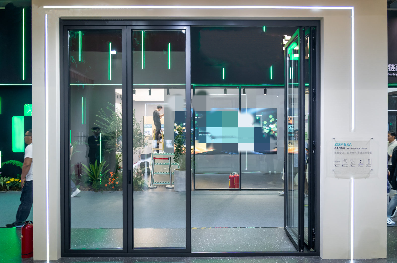
What is the standard production lead time for bulk orders of folding doors?
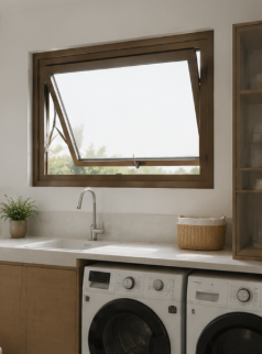
How do I choose the right Awing window size and glass specification for harsh weather?
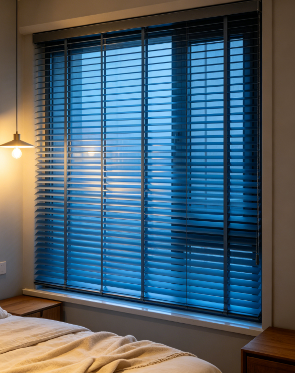
How can I test shutter samples so the final bulk order matches their quality and finish?
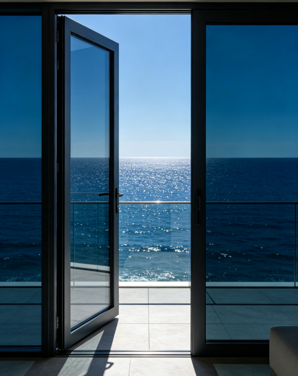
Can suppliers make custom double glass casement doors from my CAD drawings?
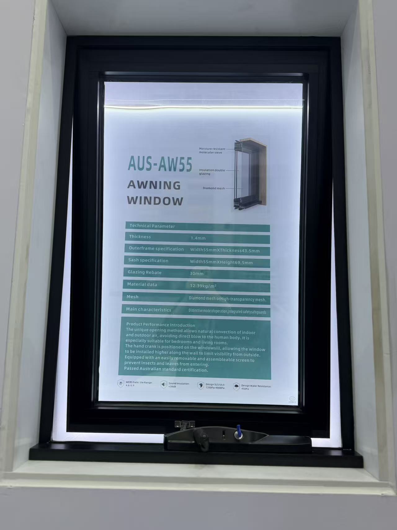
What safety certifications should I request when importing awning windows?
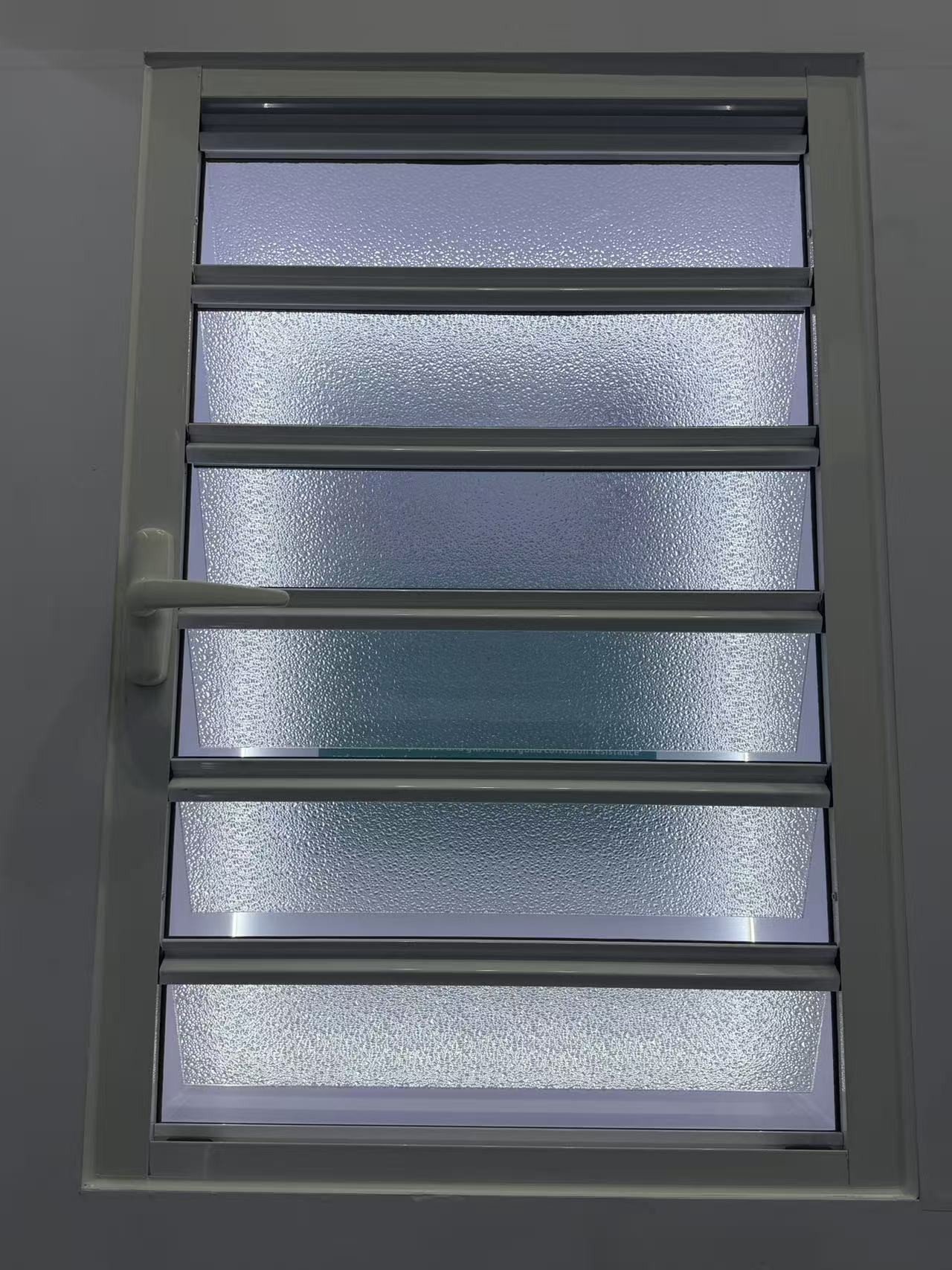
How long does it usually take a factory to make custom shutter samples?
What T-slot industrial profile size is best for a heavy duty machine frame?
How do I choose the right stainless steel decorative profile for high humidity areas?
How do I choose the right aluminum architecture profile for coastal buildings?
How do I choose the right stainless steel decorative profile for high humidity areas?
What wind load specs should I check for aluminum casement windows in coastal high-rises?
How do I know which aluminum industrial profile alloy is best for heavy machinery frames?
How do I choose the right alloy grade for aluminum architecture profiles?
How do I select the right heavy-duty hardware for exterior commercial floding doors?
How do I select the right glass thickness for bulk awing window orders?
What frame thickness is recommended for commercial aluminum casement doors?
What frame thickness is best for high-rise commercial sliding windows?
How to choose weather resistant aluminum floding door specs for commercial use?
How do I choose the best water tightness rating for commercial awing windows?
How do I choose the right frame material for commercial casement doors?
How do I choose the right wind load rating for sliding windows in coastal areas?
What is the best material for outdoor decorative profiles to prevent rust and fading?
How do I choose the right track thickness for high-traffic commercial sliding doors?
How do I choose between PVC and basswood shutters for high-humidity areas?
How do I choose between double and triple glazing for casement windows in cold climates?
How do I choose the right industrial profile thickness for heavy-duty cnc machine frames?
How do I choose the right alloy for outdoor architecture profiles to prevent corrosion?
Can you design a slim frame profile for modern minimalist look?
How do I choose the right wind-resistant floding door for a coastal commercial building?
What key specs ensure a casement window can withstand heavy rain and high winds?
How do I choose the right aluminum alloy grade for heavy-duty industrial profiles?
Which alloy grade of architecture profile is best for coastal areas to resist rust?
How do you pack windows to prevent glass breakage in transit?
Are slim-frame thermal break systems replacing traditional ones?
Does the price include the matching frame and installation kit?
How do you protect our proprietary design drawings from leaks?
How do I choose the right decorative profile for high-traffic hotel lobbies?
Is your factory the actual manufacturer or a trading partner?
Is it possible to 3D print a prototype before cutting steel?
Do you outsource any part of the painting process to others?
How do you handle replacement parts for damaged track rollers?
Do you accept escrow payments through third-party platforms?
Do you have ISO 9001 certification for your production line?
Are there extra fees if we pay via bank telegraphic transfer?
What is the price difference between powder coat and anodized?
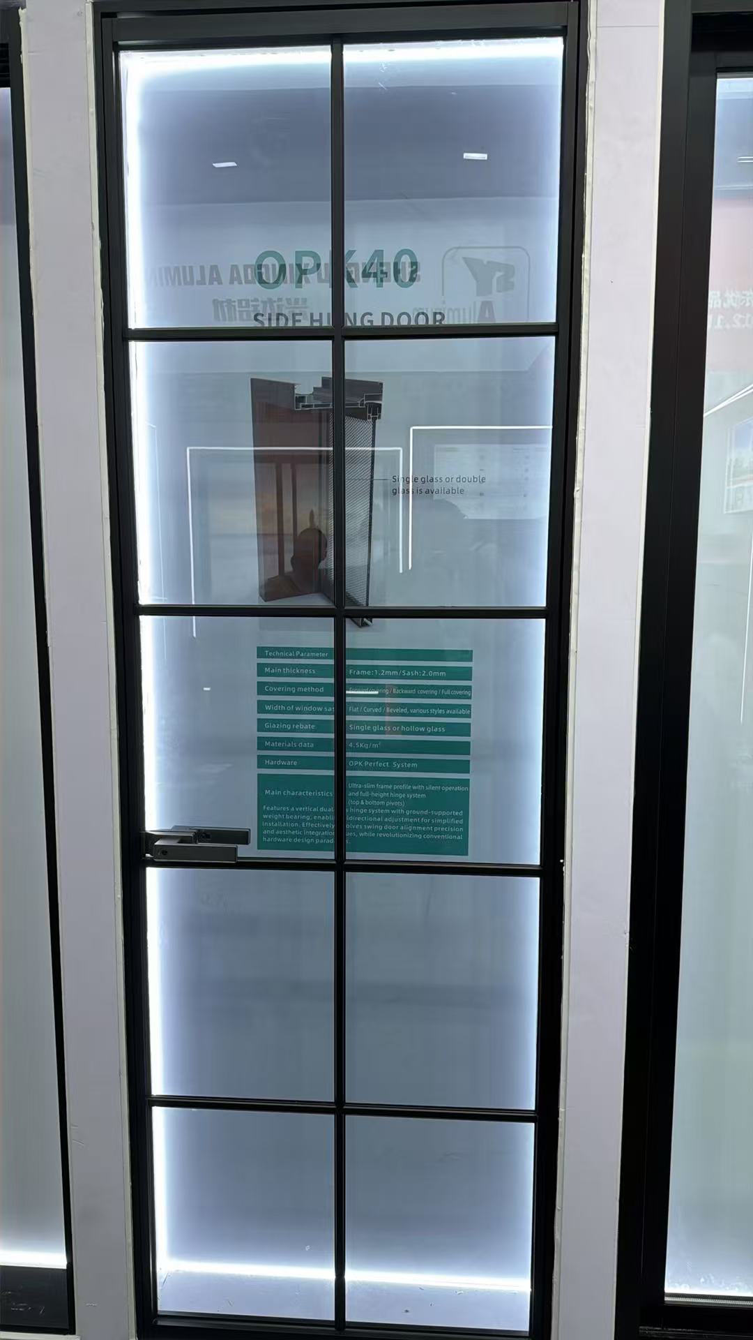
What is the warranty period for the lock and hinge hardware?
What is your policy for dimensional deviations in the batch?
What happens if the shipment is delayed due to factory error?
Do you offer online technical support if color fading occurs?
Is it possible to engrave our brand logo on the tension screw?
Do you offer credit terms for long-term purchasing partners?
Can you palletize the shipments for easy forklift unloading?
What are the latest eco-friendly finish trends for decorative profiles in modern interior design?
What are the tooling cost and design limitations for customizing heavy-duty industrial profiles?
Has your architecture profile manufacturing facility passed ISO 9001 certification?
Can we use Alibaba Trade Assurance for our initial sliding door order to mitigate risk?
Do you provide free corner samples of the casement window frame for color verification?
Is it possible to custom-match a specific RAL color for a decorative profile order?
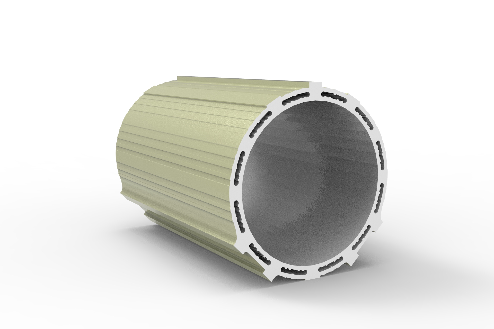
Can I request a 3D-printed sample before ordering a custom industrial profile mold?
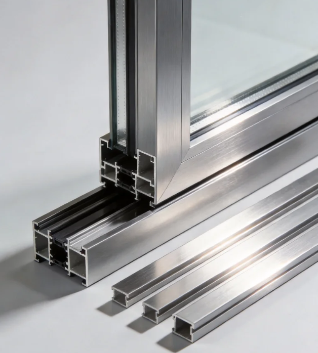
Can you extrude an architecture profile based on our proprietary CAD drawings?
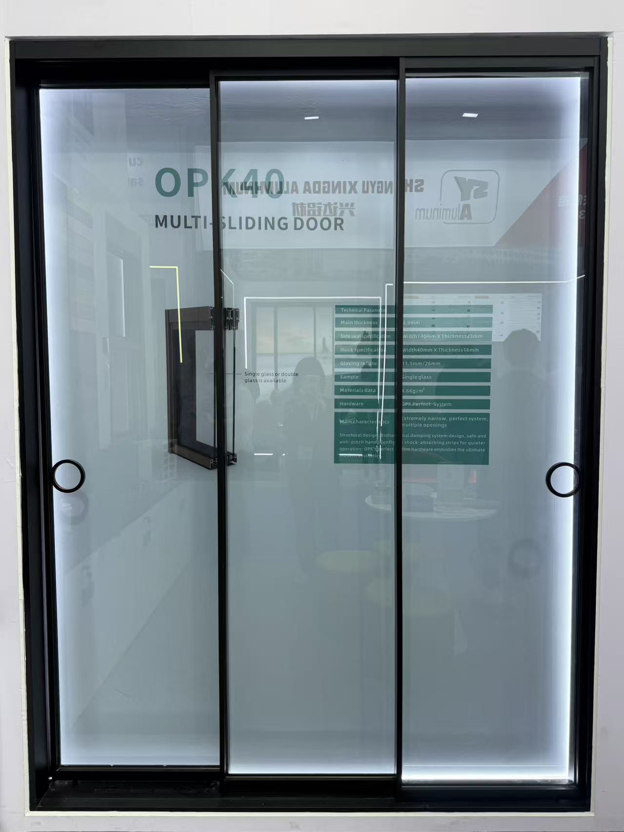
What thermal performance certifications does a sliding door need for the UK market?
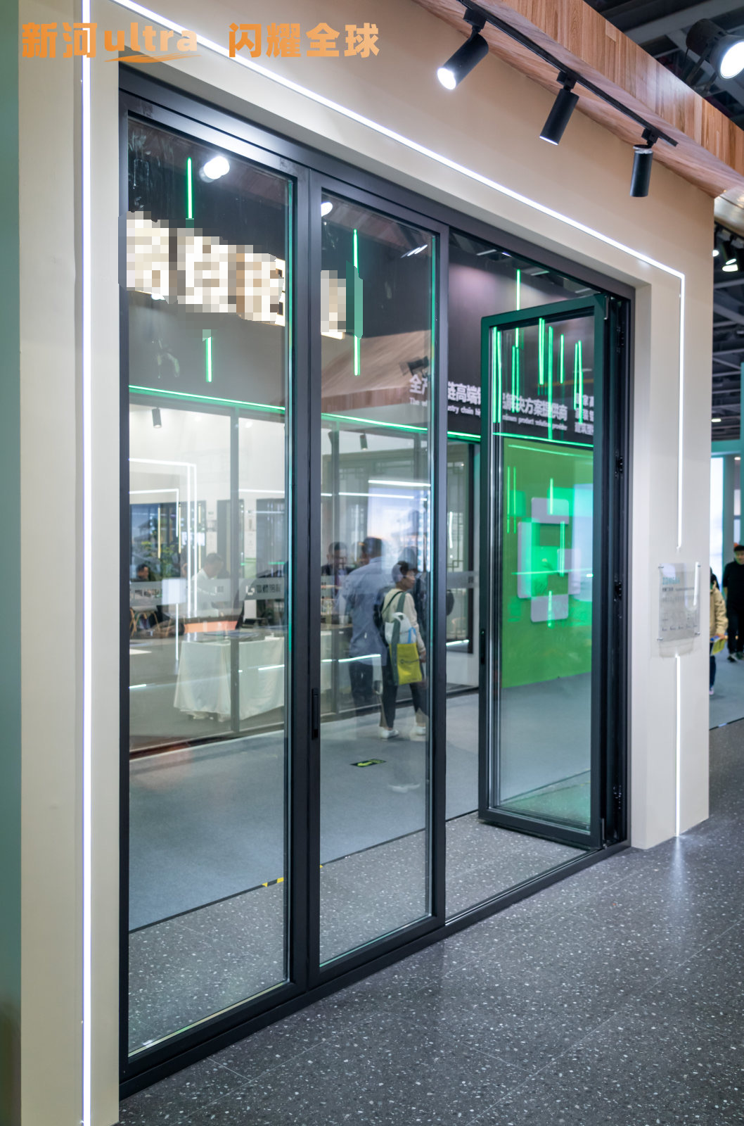
How are heavy floding door panels crated to ensure safe unloading at the job site?
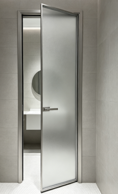
Can we arrange our own freight forwarder to pick up the casement door shipment FOB?
What is the estimated ocean freight transit time for a shutter shipment from China to Europe?
How can we source replacement seals for your awing window models in the future?
How are sliding windows typically packaged to prevent glass breakage during ocean transit?
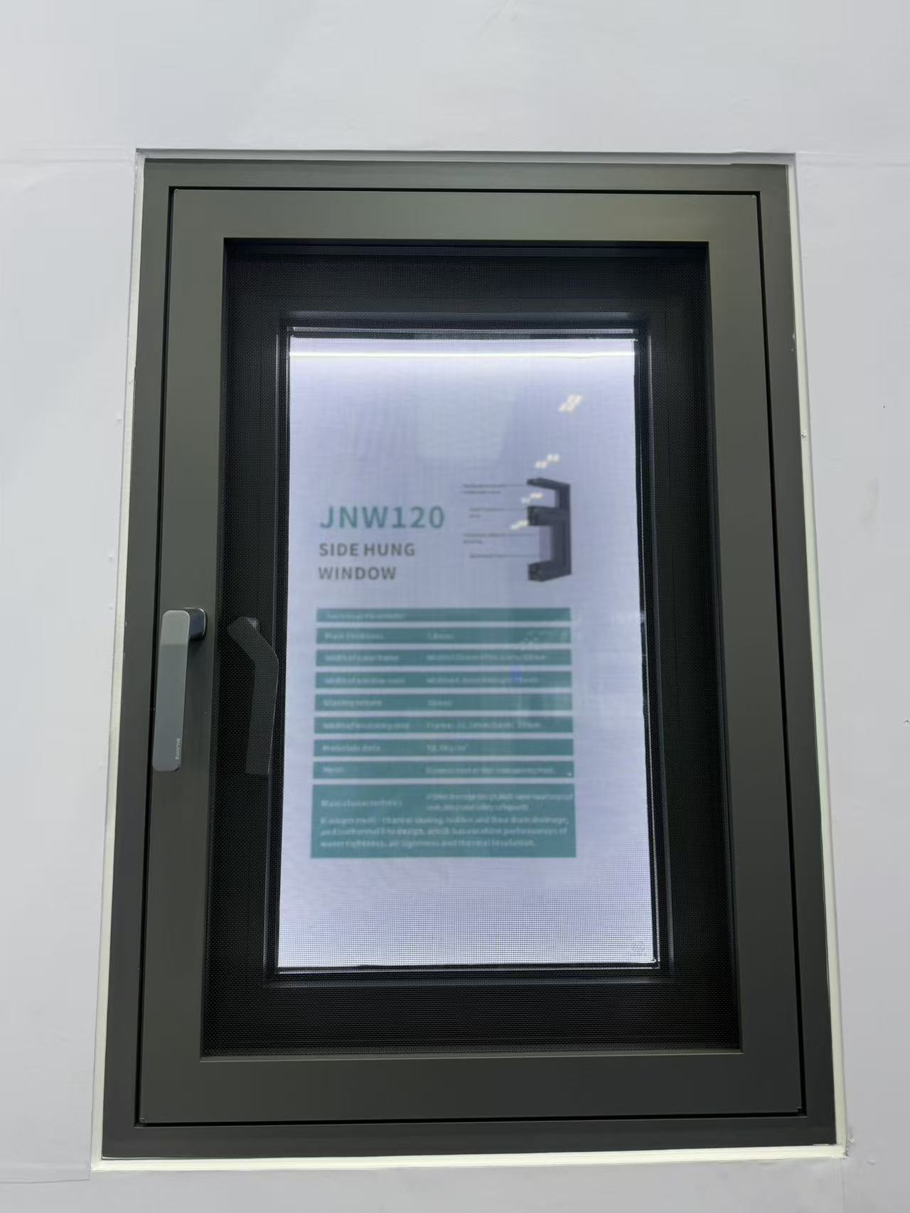
What is the average lead time for a 40ft container of standard aluminum casement windows?
Are there any extra tooling fees if my decorative profile order doesn’t meet the MOQ?
Can I get 3D printed prototypes of custom architecture profiles before committing to mold tooling?
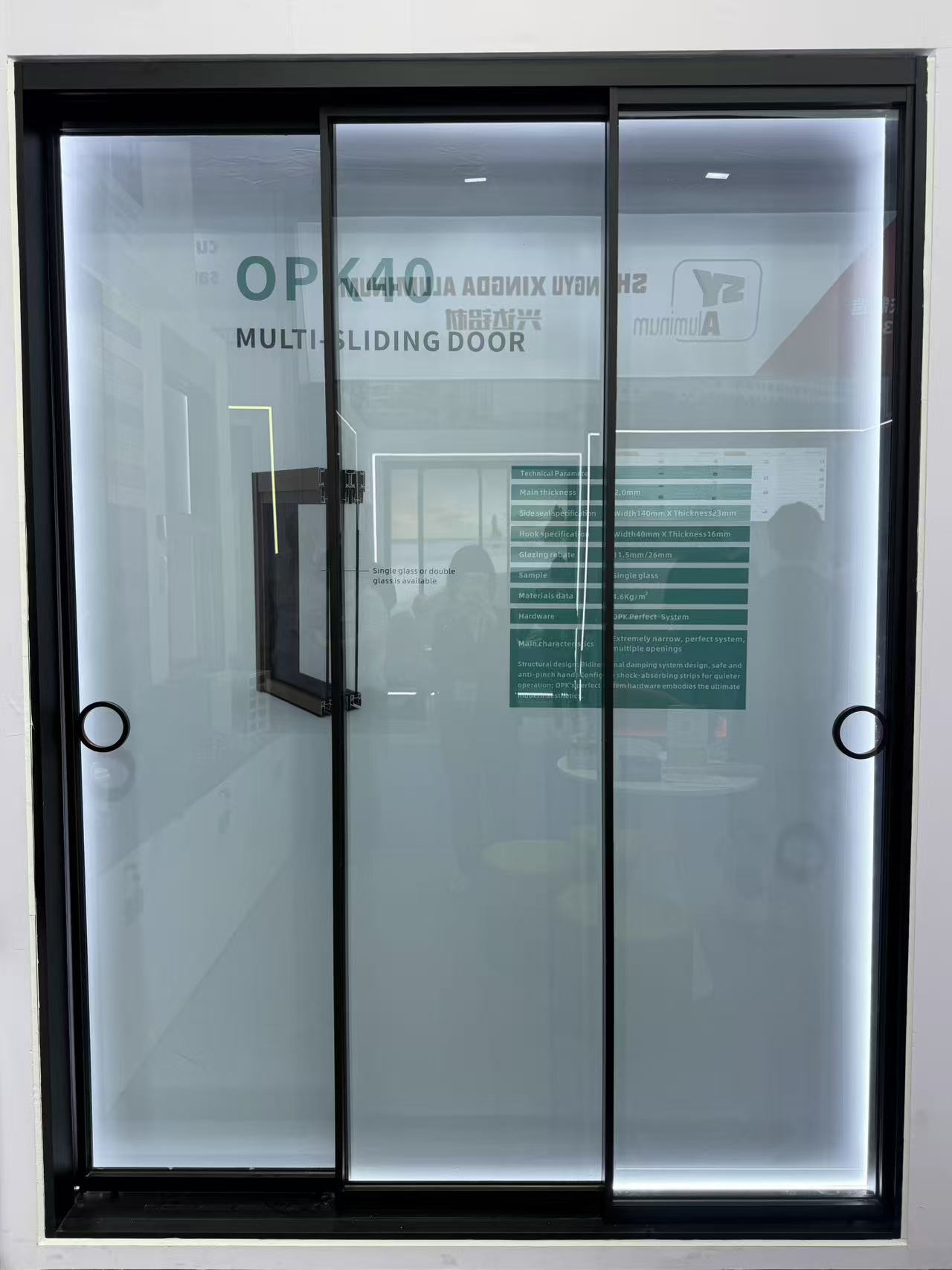
How is smart glass technology being integrated into modern residential sliding door units?
What options do you have for customizing the threshold height of an aluminum floding door?
What thermal break technology should I look for in a heavy-duty aluminum casement door?
What quality control processes do you perform on shutter hardware before final assembly?
Do you offer DDP shipping terms for awing window orders delivered to our warehouse?
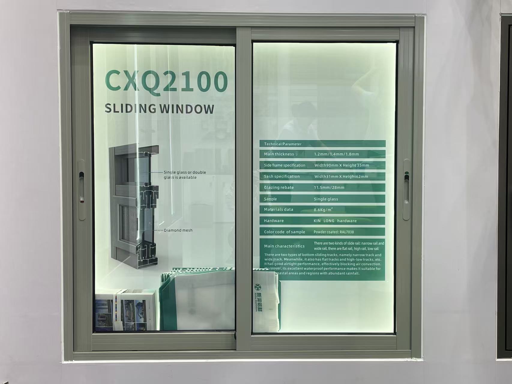
Is it possible to order a fully functional sliding window sample for mock-up testing?
Do you provide replacement hardware if the casement window hinges fail within 5 years?
How do you handle claims for decorative profile items damaged during transit?
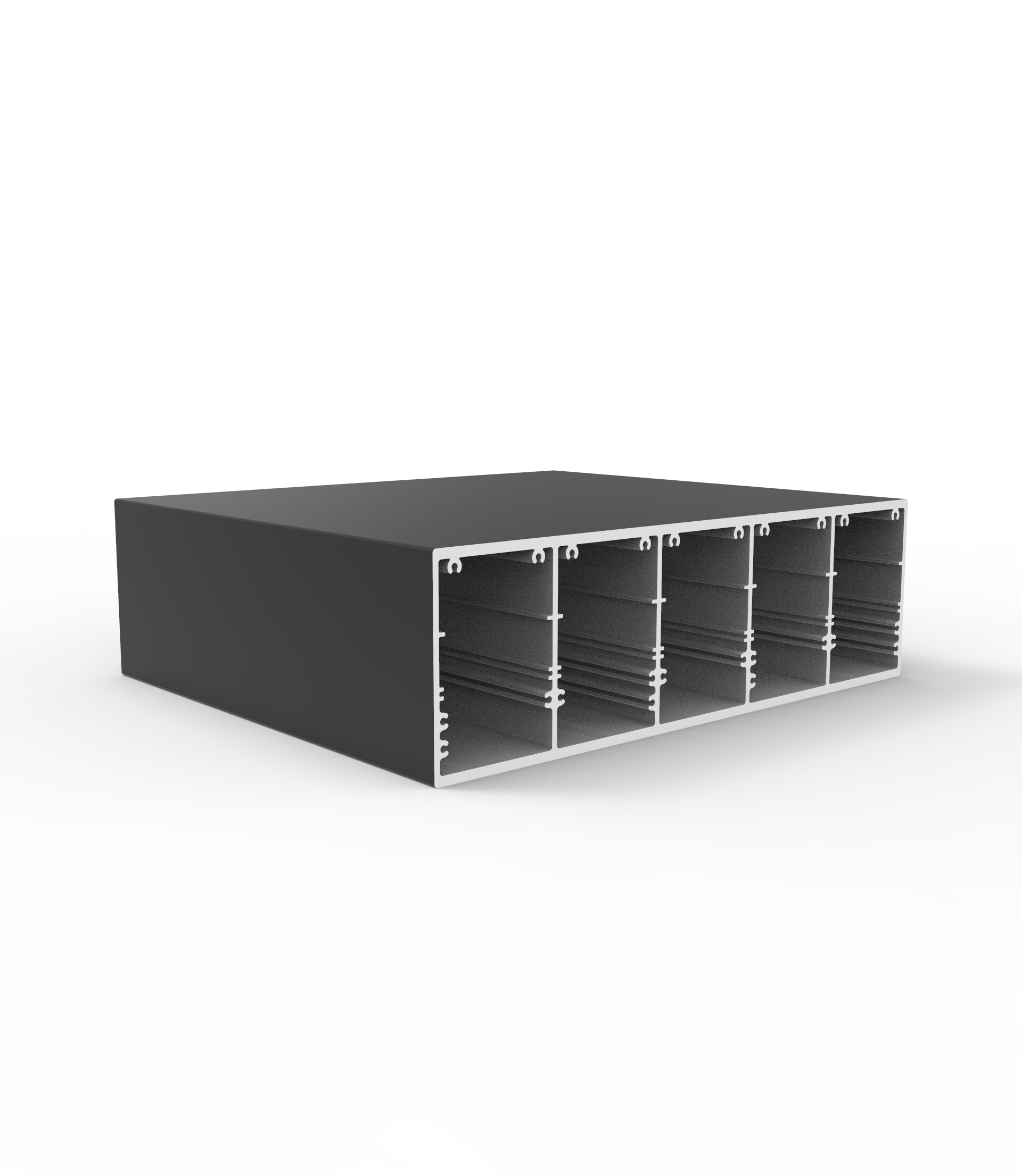
What is the standard MOQ for custom-extruded aluminum industrial profile orders?
How does the order volume affect the per-ton price of custom architecture profile designs?
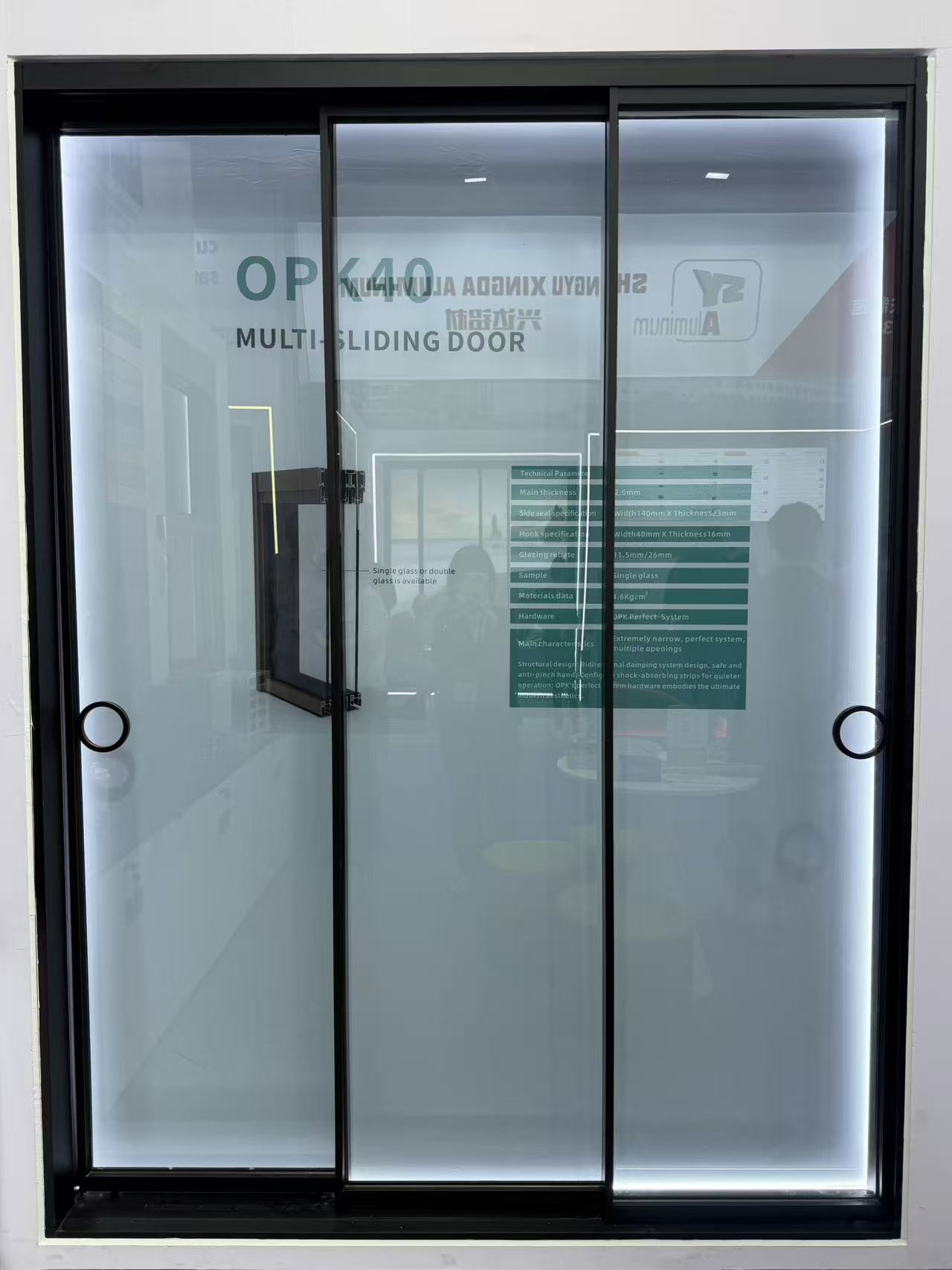
What is the warranty period for the rollers and tracks on your heavy-duty sliding doors?
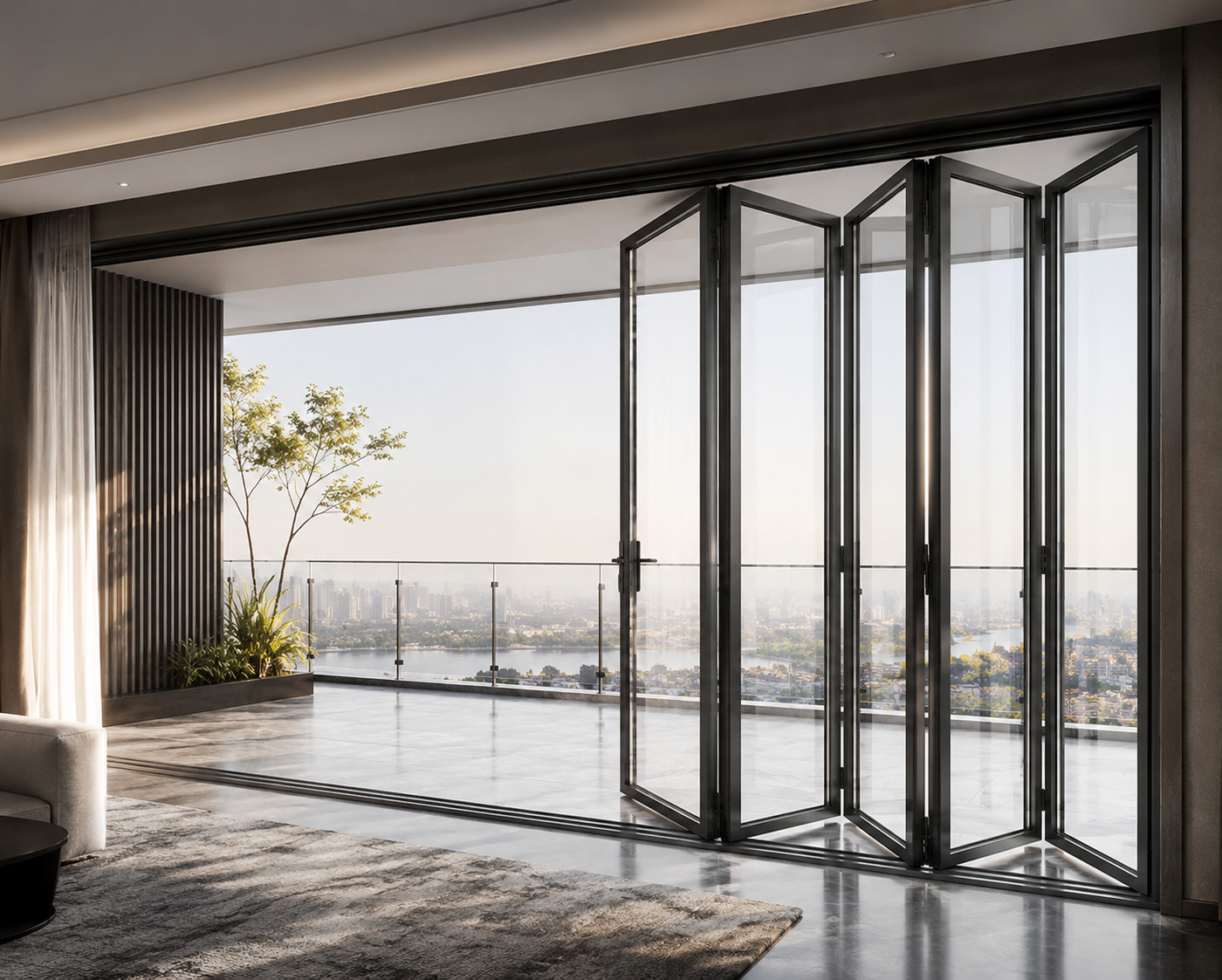
How can we secure our deposit when purchasing high-value custom floding doors from a new supplier?
Can your factory match custom anodized colors for decorative profiles based on physical samples?
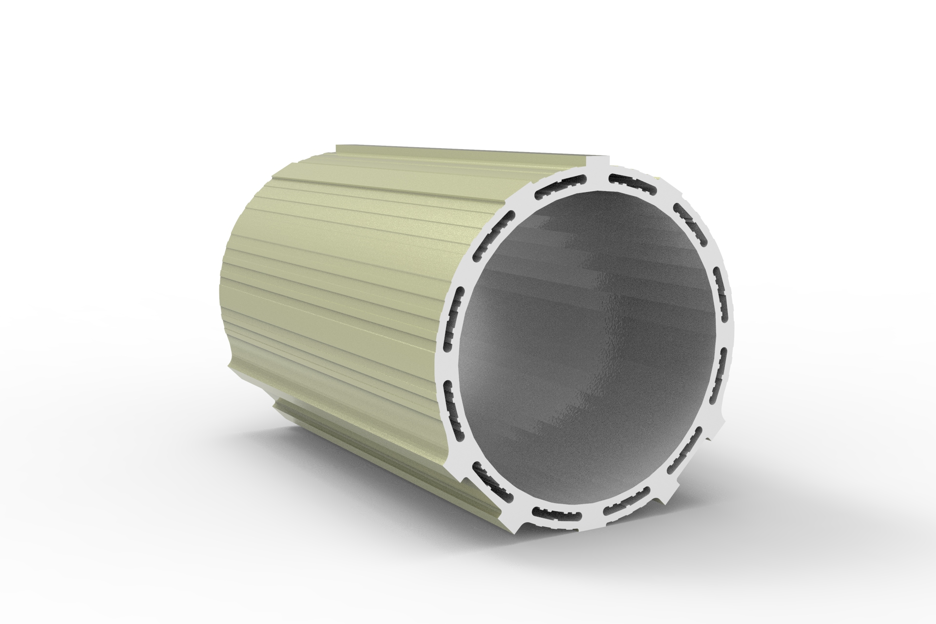
Is there a lighter alternative to aluminum industrial profile structures for robotics?
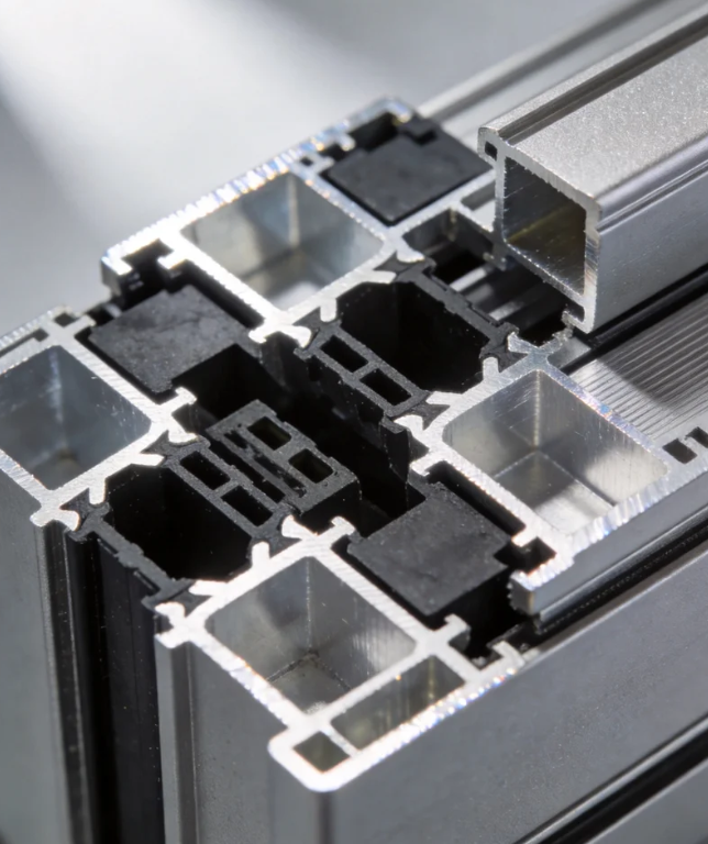
What payment security measures do you have for custom architecture profile tooling fees?
Can I order a sliding door with custom grid patterns between the glass panes?
How do you protect buyers against financial loss if the floding door shipment is delayed?
Are slim-frame aluminum casement door designs becoming more popular in modern offices?
What is your policy for replacing shutter components that arrive with color mismatch?
What kind of remote technical support do you offer for sliding window installation?
What is the maximum safe size for a top-hung awing window in commercial projects?
What environmental management standards does your decorative profile plant follow?
What is the standard lead time for producing a 40ft container of casement window orders?
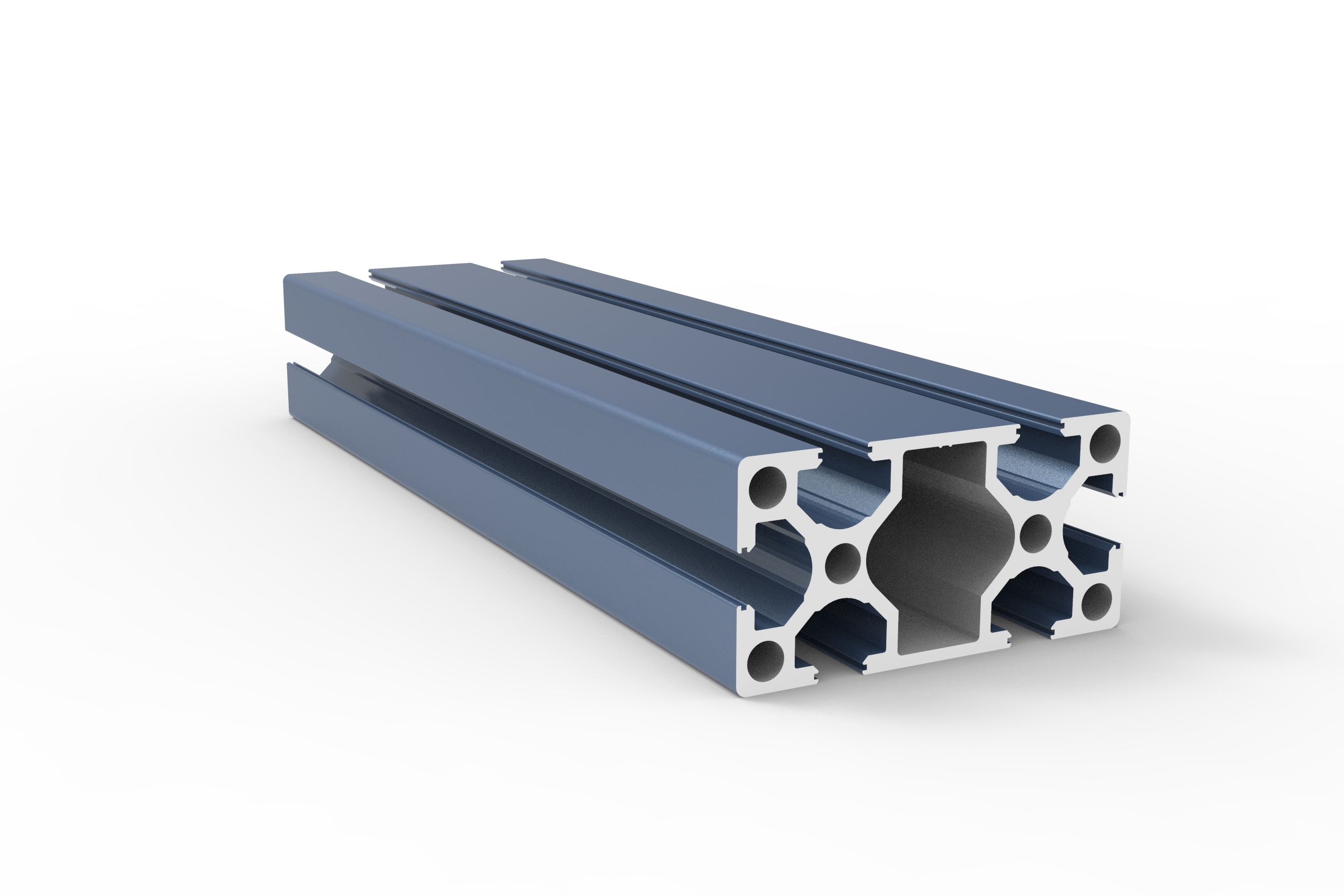
What is the warranty period for the anodized finish on your industrial profile?
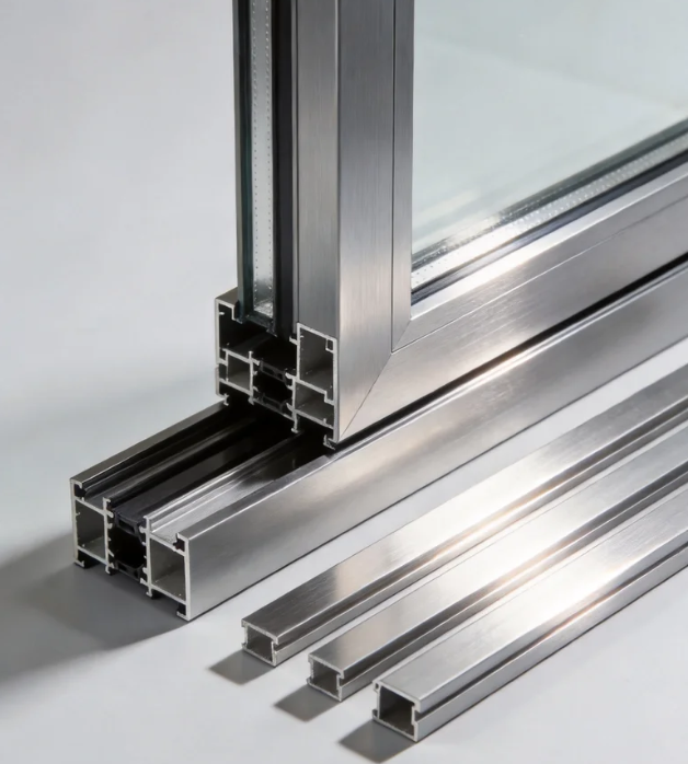
What are the latest eco-friendly trends in architecture profile manufacturing?
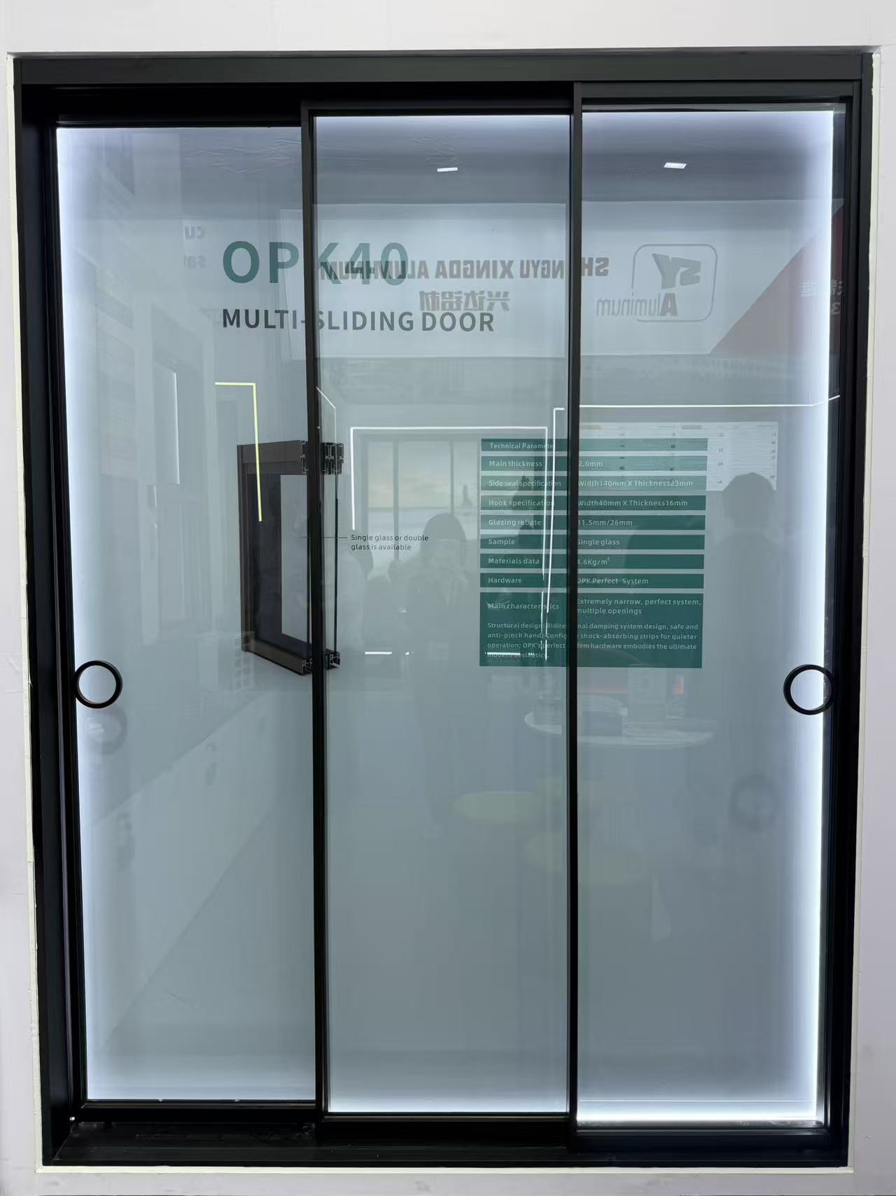
What is the average wholesale price per square meter for double-glazed sliding door systems?
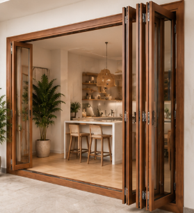
How do I calculate the structural load requirement for a 5-panel exterior floding door?
Do your exterior shutter systems comply with Florida building codes for hurricane protection?
Do you offer Letter of Credit (L/C) payment options for casement door bulk orders?
Which water tightness certifications are required for importing an awing window to Europe?
Do you allow virtual factory tours to inspect the sliding window assembly line?
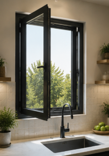
What is the typical MOQ for ordering standard-sized aluminum casement window units?
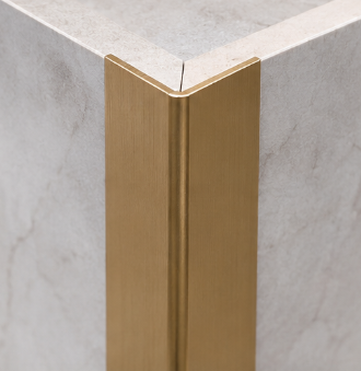
How long does it take to receive a physical sample of a gold-anodized decorative profile?
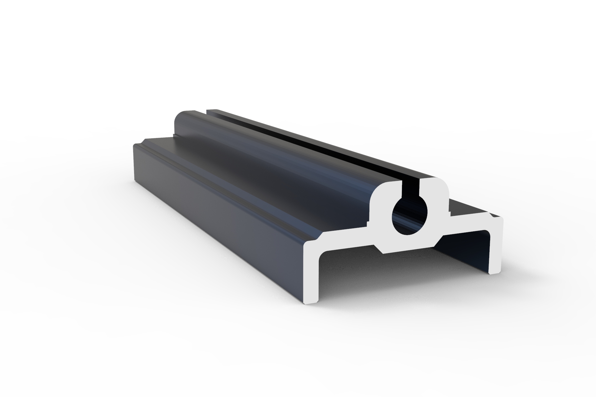
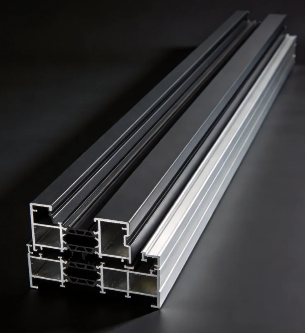
How do I choose the right alloy grade for architecture profiles in high-rise coastal buildings?
How do I choose the right track and roller specs for heavy-duty commercial sliding doors?
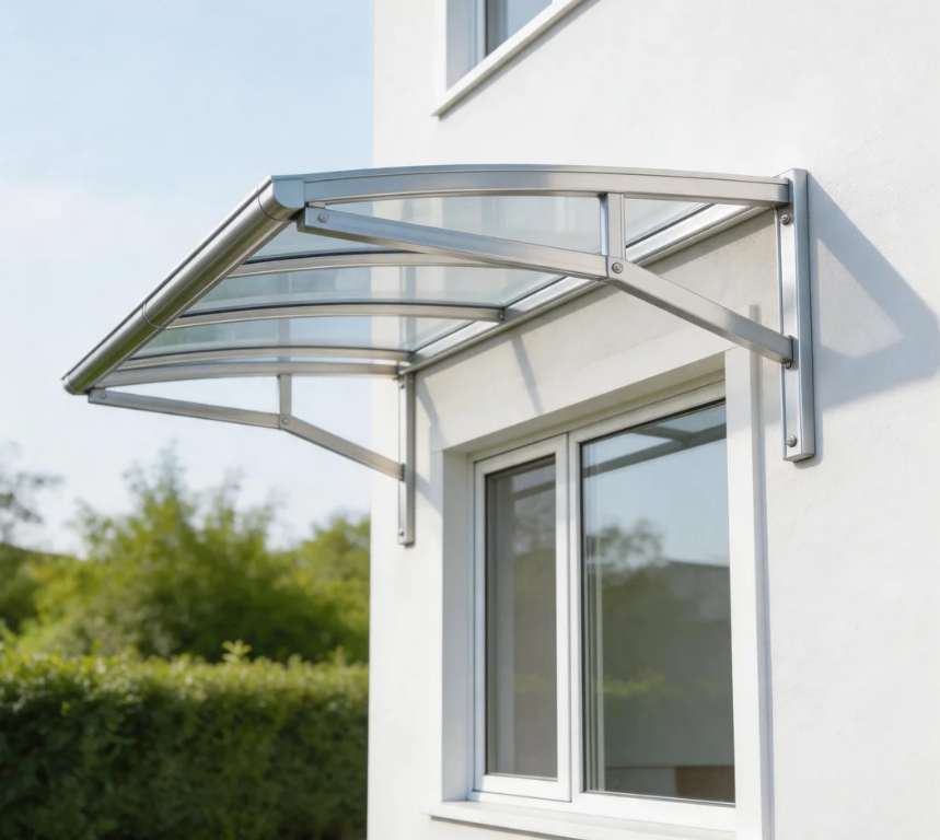
The core advantages of using aluminium profiles for the canopy
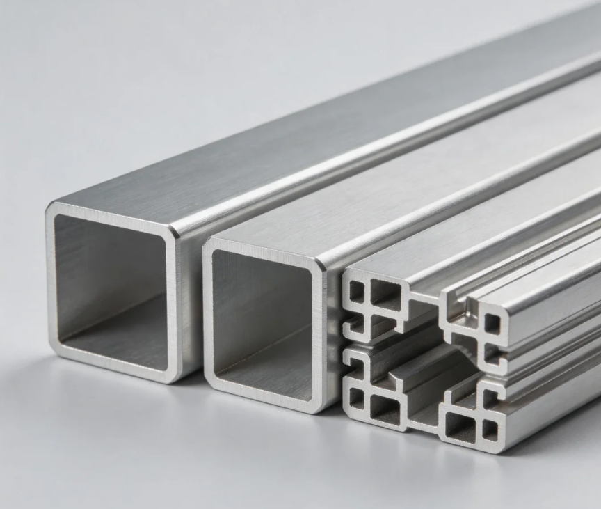
International demand: Dual drive by new energy and infrastructure
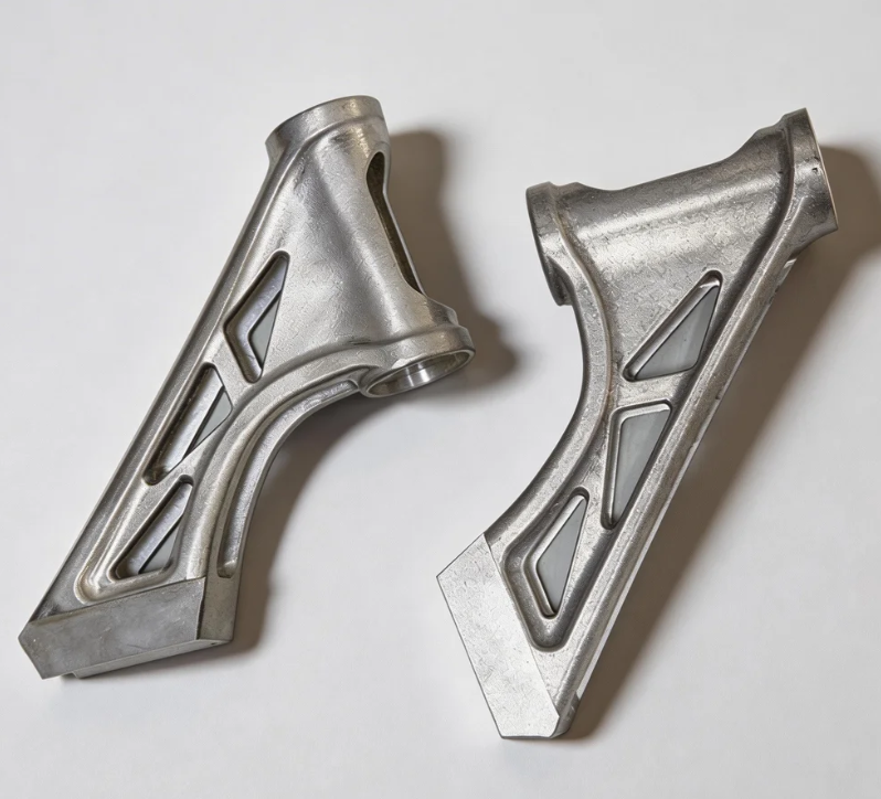

The advantages of using aluminium profiles to manufacture robot arms
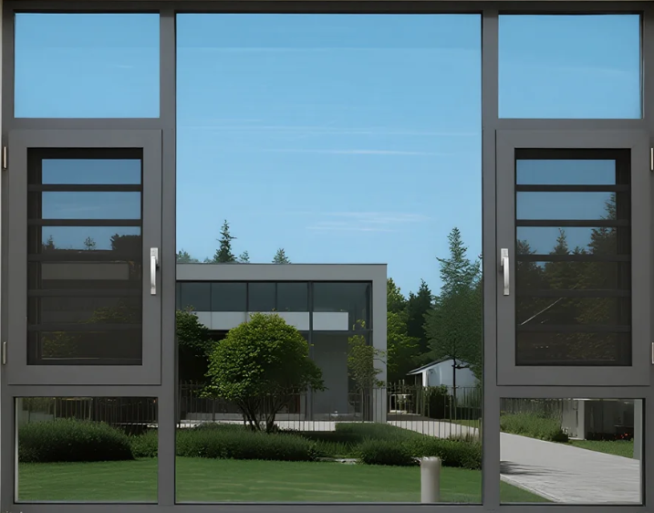
The advantages of using aluminum profiles for door and window frames
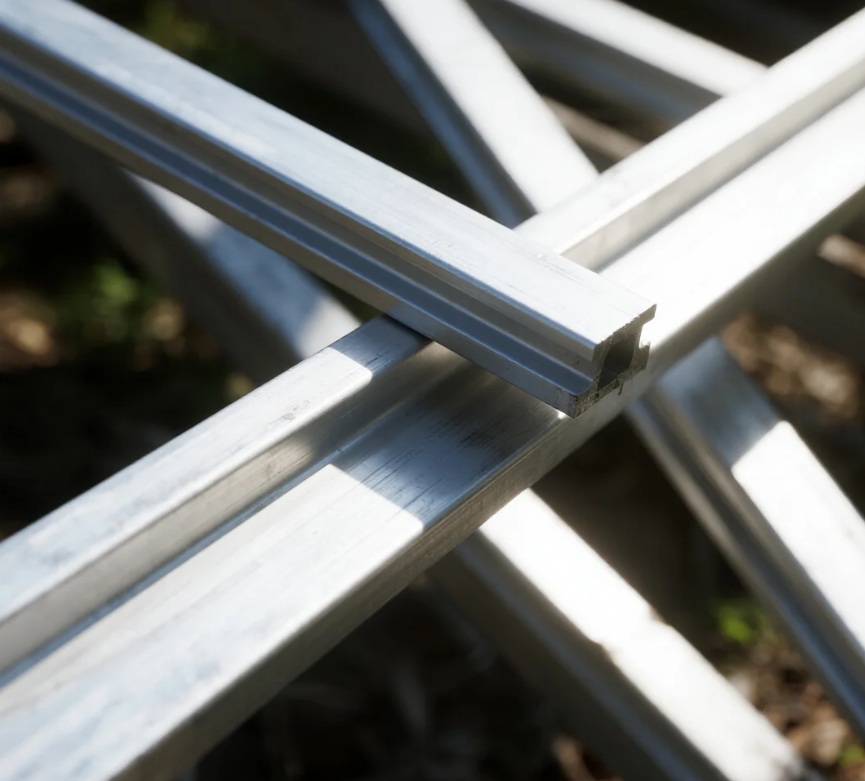
The impact of the conflict between the United States and Iran on the price of aluminum
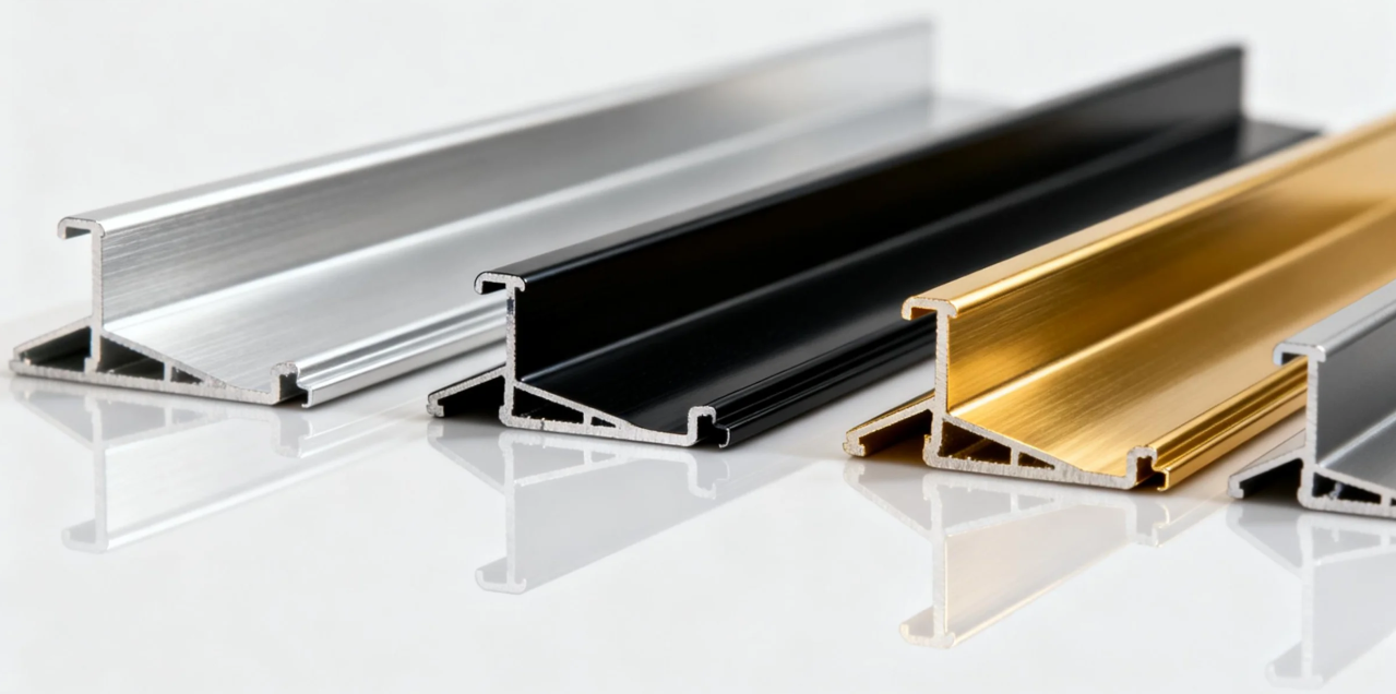
The advantages of using aluminium alloy for the main structure of high-speed train carriages


Methods for distinguishing Indoor and Outdoor Aluminium Doors
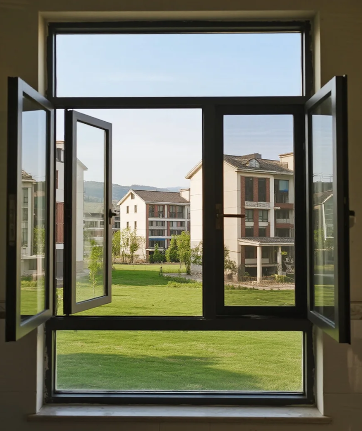
Maintenance methods and tips for aluminium doors and windows
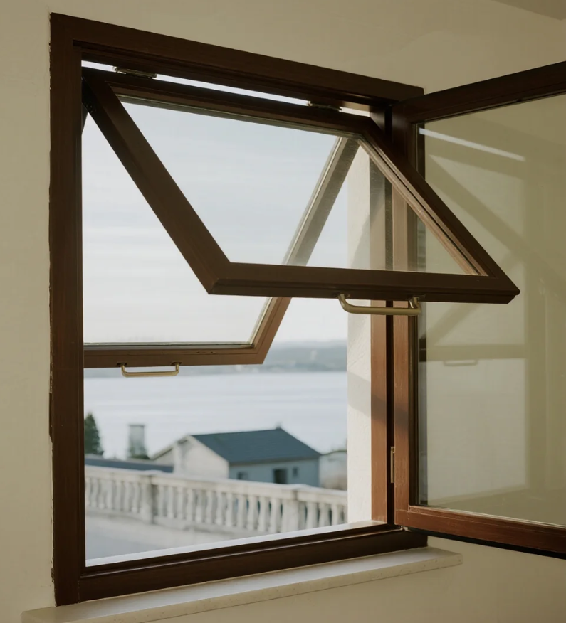
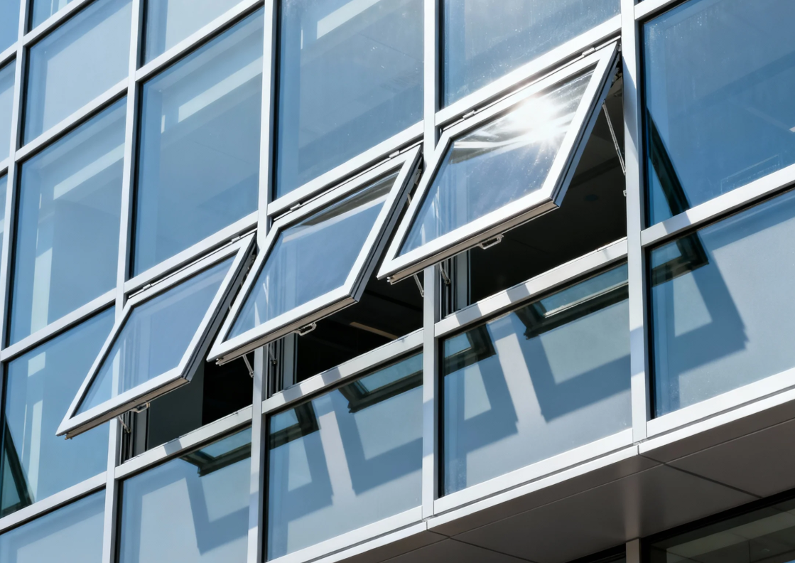
Characteristic of outward-opening and hung aluminium windows

Xinhe Aluminium Research: 7.14-7.18 Analysis of Aluminium Prices
Seven Benefits Of Using Aluminium Profiles In Curtain Wall Systems
The Application of Aluminium Profiles in New Energy Vehicles
The Composition and Application of Series 6 Aluminium Alloys
Top 5 Benefits of Using LED Aluminium Profiles in Modern Lighting
A Complete Guide to Aluminium Frame Profiles for Modern Structures
Exploring the Strength and Versatility of Aluminium Extrusion Profiles
How to Choose the Right Aluminium Profile Supplier for Your Project

COMPANY